INSTALLATION
Mounting
www.stiebel-eltron.com WPF basic | 23
10.9 Minimum flow rate of heat sink for WPF 5-16
basic
The heat pump is designed in such a way that no buffer cylinder
is required to provide hydraulic separation of the flow in the heat
pump circuit and the heating circuit in conjunction with space
heating systems.
However, in conjunction with radiators or an installation with
several heating circuits, the use of a buffer cylinder or a low loss
header is recommended.
The WPF 13 and 16 appliances must, in any case, always be op-
erated with a buffer cylinder or a low loss header.
!
Risk of damage!
The minimum flow rate to ensure perfect heat pump op-
eration must be maintained at every operating point of
the heat pump.
10.9.1 Minimum flow rate without buffer cylinder
The minimum flow rate is set using the temperature differential
of the heating system.
Set the heating circuit pump to ∆p-constant. Set ∆p-constant to a
value at which the temperature reaches or falls below the maxi-
mum temperature differential.
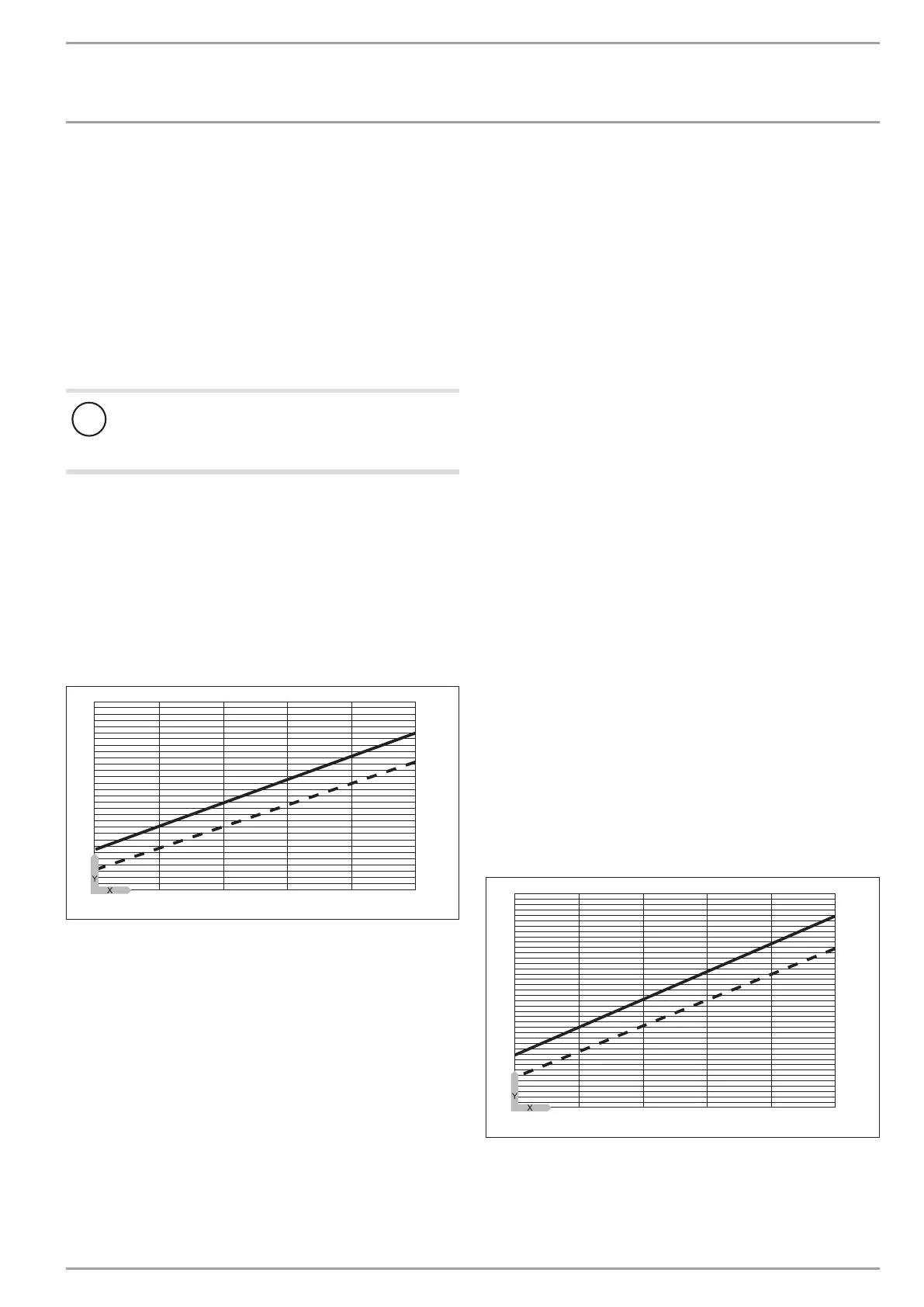
Max. temperature differential on the heating side without
buffer cylinder
1
2
18
14
16
10
12
8
6
-5 0 5 10 15 20
84�03�01�0091�
Y Max. temperature differential [K]
X Source inlet temperature [°C]
1 Heating flow 35 °C
2 Heating flow 50 °C
In heating mode without a buffer cylinder, there are two possible
ways to safeguard the minimum flow rate:
Installing an overflow valve
Install an overflow valve with an internal diameter that is matched
to and sized for the heating system, and adjust it as follows:
Fully open the heating circuit(s).
Isolate by temporarily removing the fuse from the second in-
ternal heat source (DHC electric booster heater).
Fully close the overflow valve.
Operate the heat pump in heating mode.
Set the head of the circulation pump to a level that safe-
guards the flow rate required to operate the heat pump.
Check the final setting in DHW mode and adjust if required.
Fully open the overflow valve.
Close the overflow valve one turn at a time until the return to
the heat pump or the installed radiators become noticeably
warm.
If no overflow can be detected in the overflow valve using the
temperature sensor, close the heating circuit and heating circuit
valves and check the overflow valve is working.
Individual room control via remote control FE7 or FEK
In this case, one or more heating circuits in the heating system
must be left open. The open heating circuit(s) should be installed
in the lead room (room in which the remote control is installed,
e.g. the living room). The individual room can then be controlled
via the FE7 or FEK remote control, or indirectly by adjusting the
heating curve. The other rooms can be equipped with zone valves
or thermostatic valves.
Fully open the heating circuit(s).
Isolate by temporarily removing the fuse from the second in-
ternal heat source (DHC electric booster heater).
Operate the appliance in heating mode.
Set the head of the circulation pump to a level that safe-
guards the flow rate required to operate the heat pump.
Check the final setting in DHW mode and adjust if required.
10.9.2 Minimum flow rate with buffer cylinder or low loss
header
The minimum flow rate is set via the temperature differential of
the buffer circuit.
Set the heating circuit pump to ∆p-constant. Set ∆p-constant to a
value at which the temperature reaches or falls below the maxi-
mum temperature differential.
Max. temperature differential on the heating side with buffer
cylinder or low loss header
12
1
2
10
11
8
9
6
7
5
4
-5 0 5 10 15 20
84�03�01�0090�
Y Max. temperature differential [K]
X Source inlet temperature [°C]
1 Heating flow 35 °C
2 Heating flow 50 °C
Isolate by temporarily removing the fuse from the second in-
ternal heat source (DHC electric booster heater).