INSTALLATION
Commissioning
www.stiebel-eltron.com WPF basic | 35
set flow temperature is compared with the captured dew point
temperature, so the actual temperature never drops below the
dew point. When using fan convectors with the FEK remote control,
set the COOLING MODE parameter to FAN.
The following settings for the FE 7 and the FEK can be selected for
the cooling operation in parameter 6:
- Room temperature
Cooling starts when the selected room temperature is ex-
ceeded (output COOLING=230 V).
Cooling is stopped, if the actual room temperature drops 2 K
below its set temperature. (output COOLING=0 V)
- Flow temperature and hysteresis
The cooling operation is regulated via the selected flow tem-
perature. The brine pump starts at:
[flow temperature + hysteresis]
Brine pump off, when the actual temperature drops below
the flow temperature.
The [flow temperature+hysteresis] should be at least 3 K <
room temperature. Lower flow temperatures cause a more
rapid cooling of the room.
As soon as, with setting AREA, the determined dew point
temperature is + 2 K higher than the selected flow tempera-
ture, that temperature will be overridden with the dew point
temperature and acts as controlled variable. The brine pump
starts at [entered or newly determined flow temp. + hyster-
esis].
The source pump stops and the cooling operation termi-
nates, if the actual flow temperature lies below the entered
or newly determined flow temperature. The cooling signal
remains active.
- Dynamic
Dynamics can be adjusted from 1 to 10. It describes the delay
between stage 1 and stage 2, whereby the second stage is
started sooner, the smaller the value.
7 HEAT-UP PROG
Heat-up program for underfloor heating systems
Never use the heat pump to dry the screed as this places such a
high demand on the heat source that the frost protection function
may respond. The electric emergency/booster heater must be used
for the heat-up program. For this, set parameters HEATING LIMIT
and DUAL-MODE HTG to 30°C and start the heat-up program.
Emergency mode cannot be enabled in the heat-up program.
There are a total of 6 parameters for the heat-up program. These
6 parameters can be adjusted in sequence as soon as the heat-up
program is activated. This program is started with the parameter
HEAT-UP PROG and with the setting ON. The system then heats
to the selected low end temperature (parameter LOW END TEMP).
The low end temperature is then held for the set period (parameter
LOW END DURAT). After expiry of this period, the system heats
with an increase K/day (parameter INCREASE/DAY) to the maxi-
mum low end temperature (parameter MAX. HEAT-UP T) and is
held at the maximum temperature via the selected time (param-
eter MAX T DURATION). After expiry of this period, the system
reduces the temperature back to the low end temperature in the
same stages as per heat-up. This concludes the heat-up program.
As soon as two heating circuits are operational, both will be op-
erated in accordance with this heat-up program (operation with
buffer cylinder and mixer circuit). Direct heating circuit 1 (buffer
circuit with return sensor) adopts the heat-up program’s set val-
ues. The actual temperature inside the buffer cylinder is higher
at the heating flow, since it is regulated via the return sensor. The
mixer (heating circuit 2) regulates the temperature back down to
the selected set values in the heat-up program (low end temper-
ature and maximum temperature).
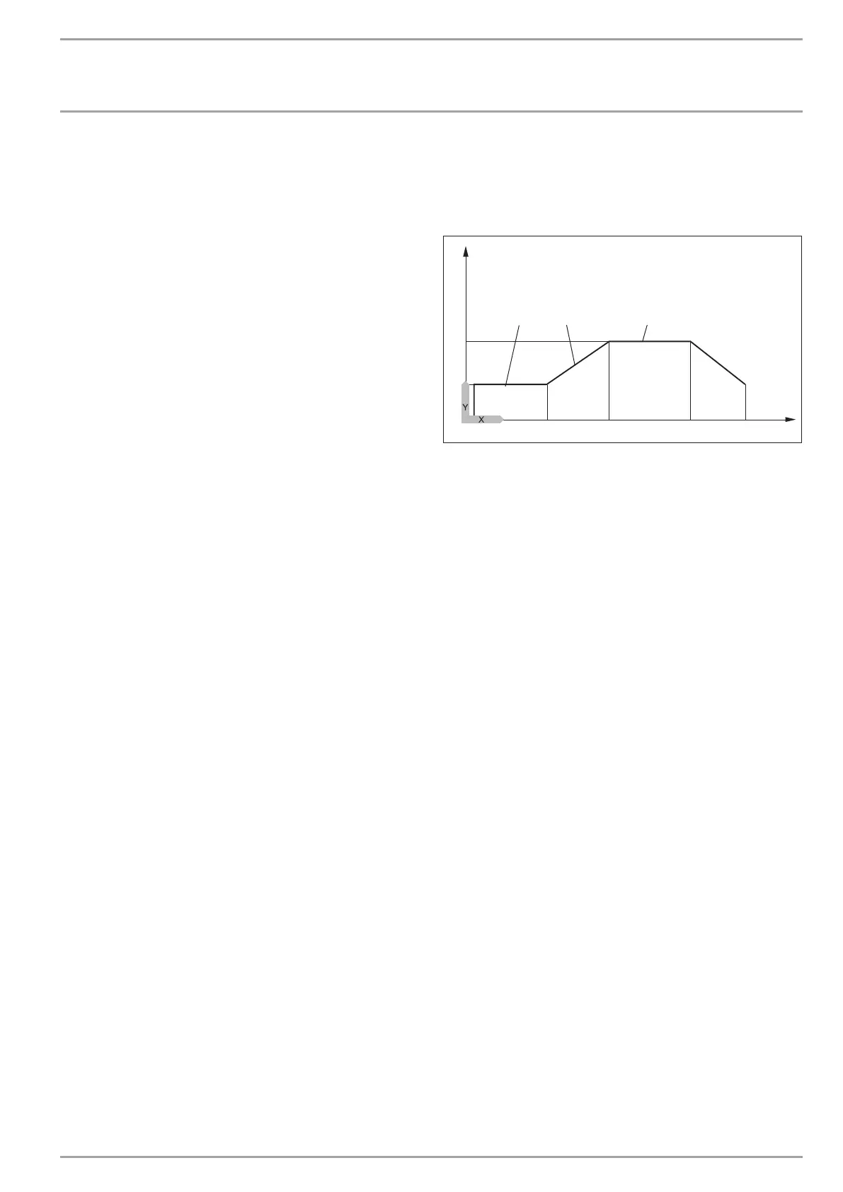
1
7
4 5
3
2
84�03�01�0038
6
Y Temperature
X Time
1 Maximum temperature
2 Low end temperature
3 Low end temperature rise period
4 Increase K/day
5 Maximum temperature duration
6 Start
7 End
Please note that only the mixer circuit pump is running when
operating with two heating circuits.
The return sensor is again used for control, when only the direct
heating circuit 1 is operational. As the actual temperature inside
the buffer cylinder is higher at the heating flow, this constellation
sees 5 K being deducted from the set heat-up program values (low
end and maximum temperatures).
The summer logic is disabled whilst the heat-up program runs
8 SUMMER MODE
The summer mode parameter allows you to select the time from
when the heating system should change into summer mode. Sum-
mer mode can be switched ON or OFF. This function offers two
adjustable parameters.
The “Building Type” parameter determines, subject to building
type (setting 1, 2 or 3), an adjusted outside temperature. If the
calculated outside temperature ≥ the selected outside tempera-
ture, both heating circuits (if installed) switch to summer mode;
reset hysteresis –1 K. SUMMER MODE is shown in the display when
the flap is closed.
With set-value control, summer mode is disabled for heating cir-
cuit 1.
OUTSIDE TEMP parameter:
Available outside temperature 10 °C to 30 °C
BUILDNG TYPE parameter:
Setting 1: Mild adjustment of the outside temperature (averag-
ing over a 24 h period), e.g. timber construction with rapid heat
transfer.