INSTALLATION
Commissioning
38 | WPF basic www.stiebel-eltron.com
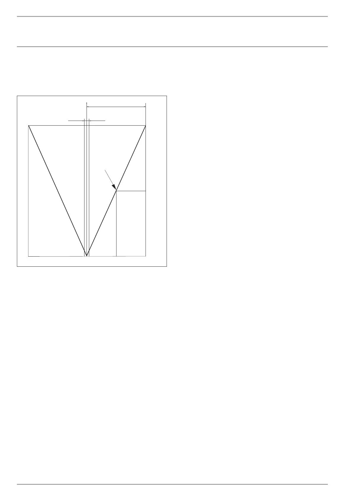
Example of setting 100 and a current control deviation of 5 K.
5 K of 10 K = 50% = ON duration
Example of a control deviation
± 1 K
4
3
C26�03�01�1067
1
2
1 Setting 100 = control deviation 10 K
2 Control deviation 5 K
3 Control deviation in K
4 ON time in %
19 FROST PROTECT
The heating circuit pumps are started at the selected frost protec-
tion temperature, to prevent the heating system being damaged
by frost; the reverse hysteresis is 1 K.
20 SELECT REM CON
Remote control FE7 can be selected for both heating circuits
The SELECT REM CON parameter can be used to preselect the heat-
ing circuit with which the remote control is to be used. Under the
parameter ROOM T 1 OR 2 at control level 2, you can scan the ac-
tual room temperature, subject to the remote control preselection.
21 FE CORRECTION
This parameter enables the calibration of the actual room tem-
perature.
22 ROOM INFLUENCE
Room influence for the FE 7 remote control unit
Standard setting 5 adjustable from ----via 0 to 20 dashes (----)
in the display:
With the FE7 remote control connected, the room temperature
sensor only serves to record and display the actual room temper-
ature; it has no influence on the actual control. Only in automatic
mode can the room temperature for heating circuit 1 or 2 be
adjusted by ± 5 °C. This set value adjustment applies to the then
current heating time, not to the setback time.
At the same time, setting “0 to 20” serves to control the room tem-
perature-dependent night setback. This means that the heating
circuit pump is switched OFF at the point of changeover from the
heating into the setback phase. It remains OFF, until the actual
room temperature falls below the set room temperature. After-
wards, the system regulates in weather-compensated mode.
If you want the room temperature to be taken into account, set
the room temperature sensor influence to > 0. The room sensor
influence has the same effect as the outside temperature sensor
has on the return temperature, only this effect is 1 to 20 times
greater by the set factor.
Room temperature-dependent return/flow temperature with
weather compensation
With this type of control, a control cascade is formed from a re-
turn/flow temperature control that is subject to both weather and
room temperature. Consequently the weather-compensated re-
turn/flow temperature control sets a default return/flow temper-
ature that is corrected by the overriding room temperature control
in accordance with the following formula:
∆ϕ
R
= (ϕ
RSET
− ϕ
RACTUAL
) * S * K
Because a substantial proportion of the control is already handled
by the weather-compensated control unit, the room temperature
sensor compensation factor K can be set lower than with pure
room temperature control (K = 20). The figure below indicates
the control method with the set factor K=10 (room influence) and
a heating curve S=1.2.
Room temperature control with weather-compensation
This type of control offers two main benefits:
Incorrectly set heating curves are corrected by the room sensor in-
fluence K; whilst the smaller factor K provides more stable control.
However, observe the following for all control units with room
temperature sensor influence:
- The room temperature sensor must capture the room tem-
perature accurately.
- Open doors and windows greatly affect the control result.
- All radiator valves in the lead room must be fully open at all
times.
- The temperature inside the lead room is the one which af-
fects the entire heating circuit.
If you want the room temperature to be taken into account, set
the room temperature sensor influence to > 0.