27
,,,.,,,,,,
/.
+3
+àHLEN
1 2 3 4 5 6 7 8 9 10 11 12 13
B1
B1
,,,.,,,,,,
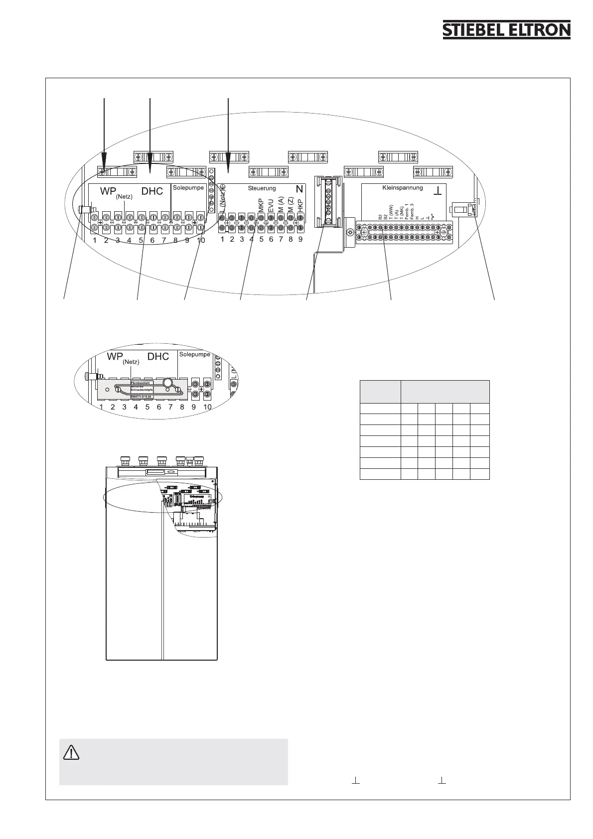
X3 Mains supply
WP Heat pump (compressor)
L1, L2, L3, PE
DHC Supplementary heater
L1, L2, L3, N, PE
Terminal
rating
Terminal allocation
2,6 kW L1 N PE
3,0 kW L2 N PE
3,2 kW L3 N PE
5,6 kW L1 L2 N PE
5,8 kW L1 L3 N PE
6,2 kW L2 L3 N PE
8,8 kW L1 L2 L3 N PE
Brine pump (Triplephase)
L1´, L2´, L3´, PE
Brine pump (Singlephase)
*
L1´, N (X3/4), PE
X4 Terminal - control
Mains supply: L, N, PE
Outputs:
ON Compressor signal
KS Brine pump signal
Kühlen Cooling mode
MKP Mixer circuit pump and N, PE
M(A) Mixer OPEN
M(Z) Mixer CLOSE
HKP Heating circuit pump and N, PE
Control inputs:
EVU Power Supply Company signal
X2 Terminal LV
B1 Temperature sensor HP flow
B1 Temperature sensor HP flow
B2 Temperature sensor HP return
B2 Temperature sensor HP return
T(WW) DHW temperature sensor and earth
T(A) Outside temperature sensor and earth
T(MK) Mixer circuit temperature sensor and earth
Fernb. 1 Remote control1
Fernb. 3 Remote control 3
H BUS High
L Bus Low
BUS Ground
“ + “ BUS “ + “
X26 (earth)X2
NX4PEX3
PE
3/PE~400/50
3/N/PE~400/50
1/N/PE~230/50
Provide separate fuses for the three
power circuits HP, supplementary
heater and control.
C26_03_01_0268
Wiring diagram WPF 5 / 7 / 10 / 13 / 16 (Triplephase)
When a single phase brine pump is connected, protect
the heat pump and the DHC only via one common RCD
breaker. N (X3/4) from the heat pump supply must be con-
nected, if no DHC is connected.
*
Fig.10

 Loading...


