35MS 201, MS 201 C, MS 201 T, MS 201 TC
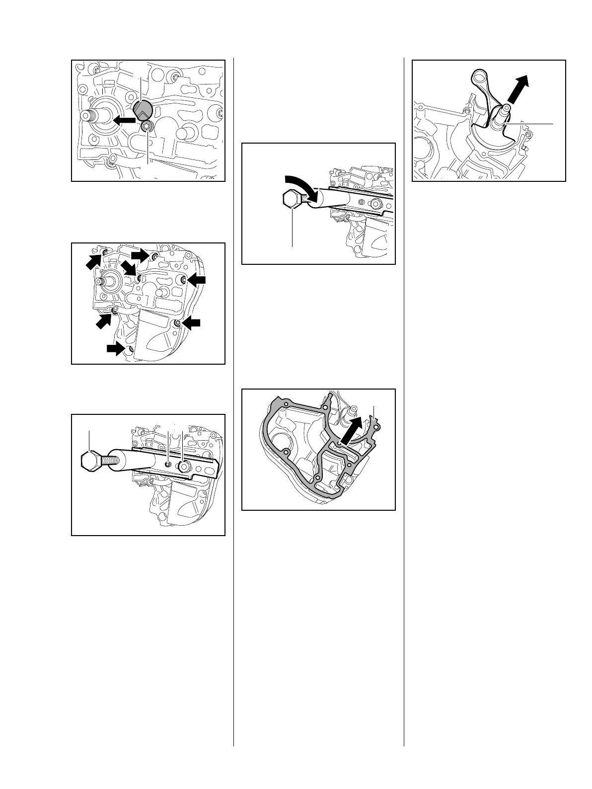
: Push out the connector (1) and
take out the screw (2).
: Take out the screws (arrows).
: Back off the spindle (1) in the
puller until it is clear of the
crankshaft stub.
Locate the service tool so that the
spindle is centered on the
crankshaft stub.
1
7013RA530 TG
2
7013RA531 TG7013RA533 TG
1
32
: Push the service tool
5910 890 2205 on to the collar
screw, screw home the screw (2),
fit the nut (3) and tighten it down
firmly.
: Turn the spindle (1) clockwise
until the crankcase is released.
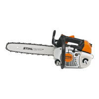
– Remove the service tool.
– Pull off the clutch side of the
crankcase.
: Remove the gasket (1).
7013RA534 TG
1
7013RA480 TG
1
: Pull out the crankshaft (1).
The crankshaft, connecting rod and
needle bearing form an inseparable
unit.
– Inspect the two halves of the
crankcase and replace if
necessary, b 6.5
– Install new bearings, b 6.5.1
– Clean the crankshaft, b 14
Take care not to damage the
crankshaft stubs.
Inspect and clean the sealing faces
on both halves of the
crankcase (including the cylinder
sealing face) – the sealing faces
must not be damaged in any way,
b 14.
7013RA481 TG
1