44 MS 201, MS 201 C, MS 201 T, MS 201 TC
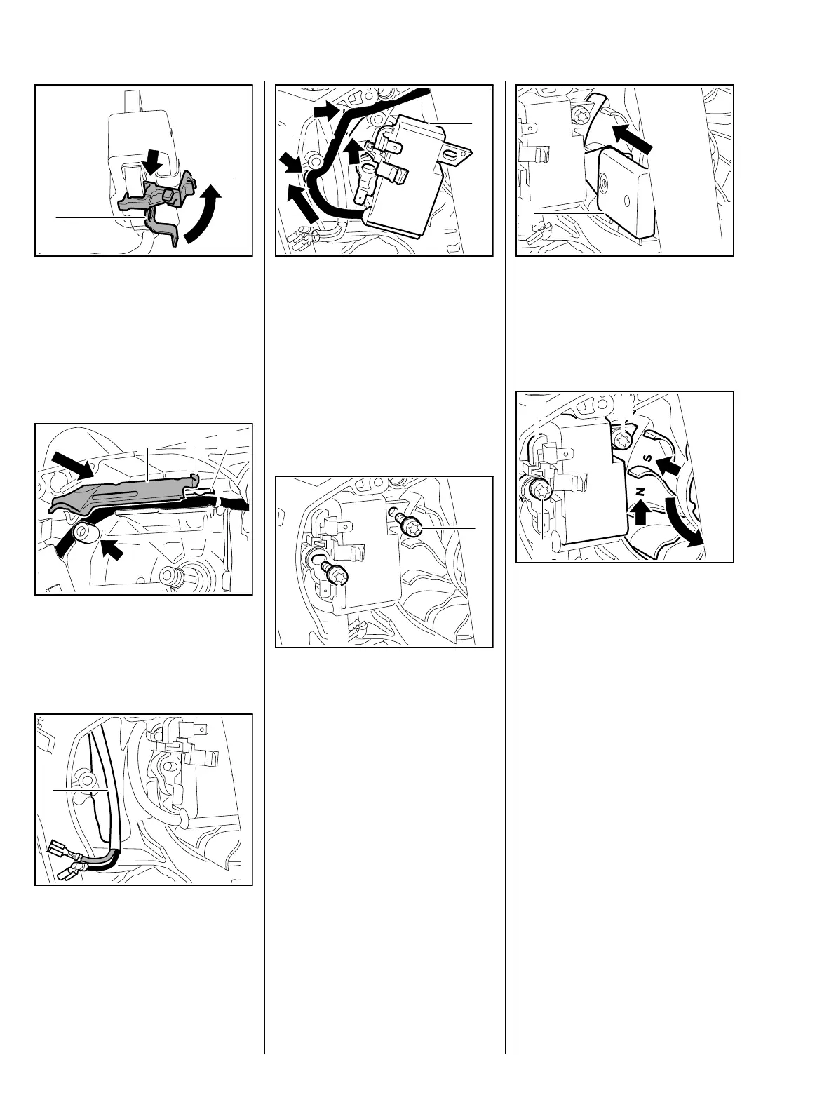
: Push the cable retainer (1) with
connector tag (2) onto the
ignition model until the tab
(arrow) snaps into position
– retainer and connector tag are
now secured to the ignition
module.
: Position the cover (1) so that the
peg (2) engages behind the
crankcase rib (3) and locates
against the boss (arrow).
: The wiring harness (1) must be
positioned in the crankcase
recess.
7013RA374 TG
2
1
7013RA375 TG
1 32
7013RA376 TG
1
: Fit the ignition lead (1) behind the
ignition module (2) so that it
locates in the guides (arrows) in
the crankcase – the ignition
lead (1) must form a loop at the
high voltage output and must not
be kinked.
: Fit the ignition module (2)
– do not pinch the wiring harness.
: Fit the screws (1) with washers
– do not tighten down yet.
– Install the flywheel, b 7.5
7013RA377 TG
2
1
7013RA378 TG
1
1
: Push the ignition module back
and slide the setting gauge (1)
1111 890 6400 between the arms
of the ignition module and the
flywheel magnet poles.
The setting gauge is not shown in
the illustration.
– The flywheel must turn freely.
: Rotate the flywheel until the
magnet poles (arrows) are next to
the ignition module (1).
– the setting gauge is in position.
: Press the ignition module (1)
against the setting gauge and
tighten down the screws (2)
firmly.
– Remove the setting gauge.
– Check operation
– Rotate the flywheel and make
sure it does not touch the ignition
module.
7013RA379 TG
1
7013RA380 TG
2
2
1