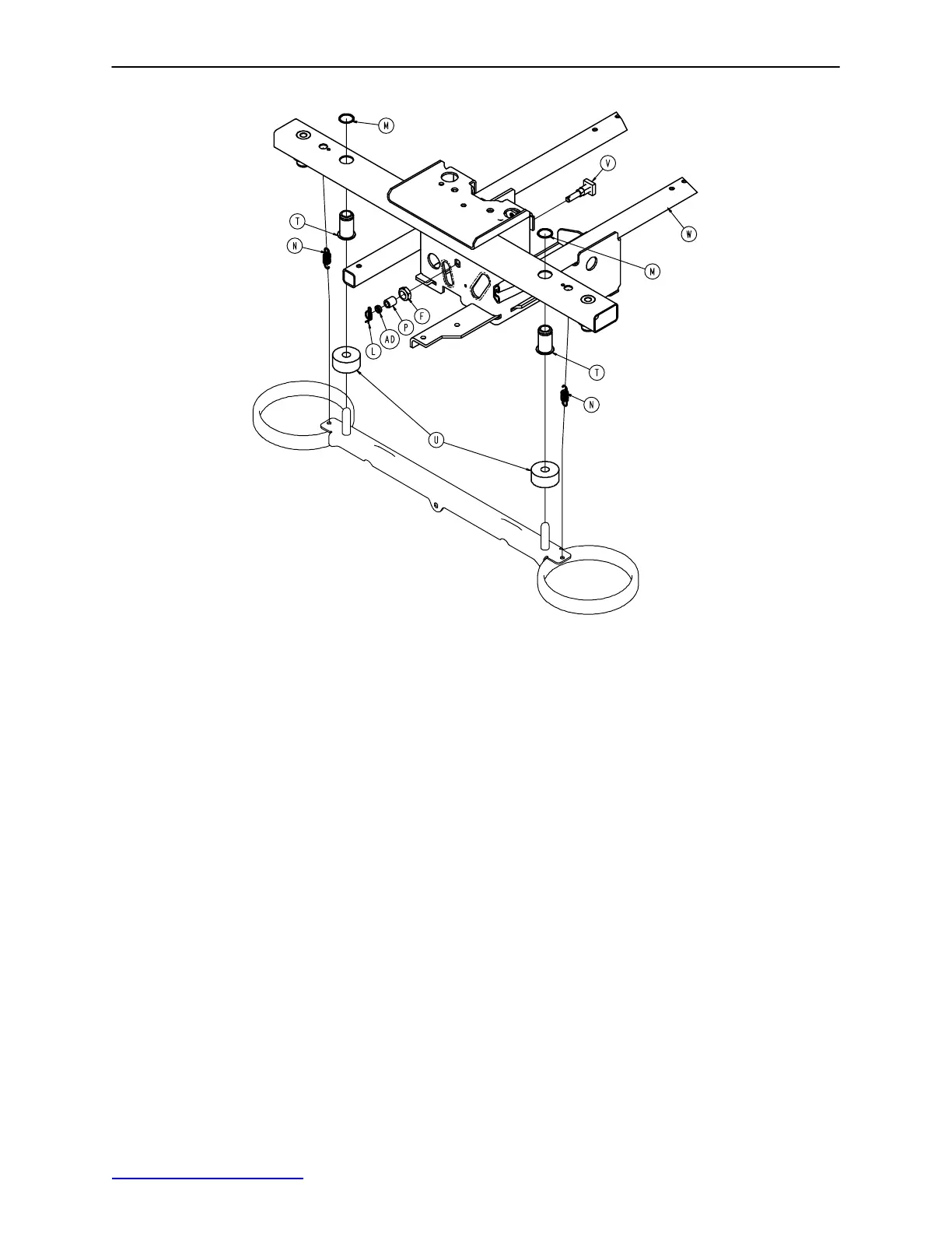
Side Control Brake Assembly
40
Typical Assembly Both Ends
Item Part No. Part Name Qty.
A 0003−364−000 Slotted Screw 1
B 0005−044−000 Step Bolt 4
C 0011−262−000 Washer 4
D 0013−018−000 Tooth Lock Washer 1
E 0016−035−000 Nylock Hex Nut 4
F 0016−049−000 Nylock Hex Nut 2
G 0023−233−000 Hex Washer Head Screw 8
H 0026−340−000 Clevis Pin 1
J 0027−012−000 Hitch Pin 2
K 0027−022−000 Rue Ring Cotter 1
L 0027−022−000 Rue Ring Cotter 2
M 0028−205−000 Spiral Retaining Ring 4
N 0038−439−000 Extension Spring 4
P 0081−272−000 Needle Bearing 2
R 0753−003−066 Clevis Pin 2
T 0753−003−079 Caster Tube Brake Pin Guide 4
U 0753−003−121 Brake Cushion 4
V 0853−003−230 Bearing Pivot Support 2
W 0853−001−001 Base Weldment 1
Y (page 42) Side Control Brake Sub−Ass’y 1
AA (page 41) Brake Rod/Side Control Ass’y 1
AB 0853−005−087 Return Spring Hook 1
AC 3001−200−052 Ground Chain 1
AD 0753−003−131 Spacer 2
Return to Table of Contents
 Loading...