Do you have a question about the Strymon CONDUIT and is the answer not in the manual?
Conduit operates in standalone mode for distributing MIDI data via 1/4" TRS and DIN OUT ports.
Conduit acts as a USB MIDI interface, exposing TRS jacks and DIN pair as independent MIDI devices.
Describes the 5-pin DIN MIDI IN/OUT ports, their function, and data flow.
Explains the function of the status LED for MIDI IN/OUT ports and its color indications.
Details the power requirements for the 9VDC input, including adapter specifications.
Explains the USB port for computer connectivity and its relation to MIDI data distribution.
Explains the SET button for jack configuration and status display.
Explains that Activity LEDs blink the color of the selected mode when MIDI data is present.
Describes the four 1/4" TRS MIDI I/O jacks and their configuration capabilities.
Default setting for Strymon pedals; sends MIDI at TIP and receives at RING.
Sends MIDI at the RING and receives at the TIP.
Sends MIDI at both TIP and RING; used for connecting two pedals to one jack.
Sends MIDI OUT only with RING as source and TIP as sink.
Press and hold SET button while connecting power to enter jack configuration mode.
Release SET button, plug/unplug cable into desired jack to change configuration.
Press SET button to save and exit TRS jack configuration mode.
Connect a 9V DC center-negative power supply (at least 50mA) to the 9VDC input.
Connect a 5-pin DIN MIDI cable from the MIDI OUT of controller to the MIDI IN port on Conduit.
Connect 1/4" TRS cable from Conduit's 1/4" I/O jack to pedal's MIDI control input.
Configure the connected pedal to communicate on the desired MIDI channel.
Optionally disable MIDI OUT from pedal unless bi-directional communication is desired.
Configure the desired 1/4" TRS jack for Tip and Ring Send (AMBER LED).
Connect the TRS end of a splitter cable to the jack set to Tip and Ring Send.
Connect the other ends of the TRS splitter cable to the 1/4" MIDI jacks on the desired pedals.
Configure connected pedals to receive MIDI via TRS on the desired MIDI channel.
Explains how Conduit MIDI Ports 1-6 map to 1/4" TRS jacks, DIN ports, and configuration port.
Tape the drill template to the desired location on the pedalboard.
Drill through the marked hole locations with a 1/8" (3mm) bit.
Place Conduit over holes and secure with #4-40 3/8" screws from the reverse side.
Details MIDI CC messages sent via Conduit Port 6 to remotely change TRS jack configuration.
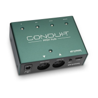
Lists key features of the Conduit, including connectivity and build.
Provides technical specifications like power, weight, and dimensions.
Lists all items included in the Conduit package.
Indicates this appendix covers standalone operation without USB connection.
Illustrates cable connections for Conduit in standalone MIDI distribution.
Illustrates the flow of MIDI data in standalone mode without a USB connection.
Introduces the functionality of Conduit as a USB MIDI interface.
Illustrates cable connections for Conduit when used as a USB MIDI interface.
Illustrates the flow of MIDI data when Conduit is connected to a computer via USB.
Covers defects in material and workmanship for two years from purchase.
Lists conditions not covered by the warranty, such as misuse or natural disasters.
Outlines limitations on Strymon's liability for product failure or damages.
Provides instructions for obtaining warranty repair service in North America and internationally.
| Type | MIDI Hub |
|---|---|
| Connectivity | USB, MIDI |
| USB Ports | USB-B |
| Power | 9V DC center-negative, 300mA minimum |
| Polarity | Center Negative |
| Function | MIDI Routing, MIDI Thru, MIDI Filtering, MIDI Mapping, MIDI Merging, MIDI Splitting |
| Connection | USB |
| Compatibility | MIDI Devices |
| Build | Metal Enclosure |