Do you have a question about the Stulz CyberCool and is the answer not in the manual?
Explanation of safety symbols including DANGER, WARNING, CAUTION, NOTICE, ESD NOTE.
General safety guidelines for installation, operation, and maintenance by competent staff.
Precautions and procedures for safe handling of refrigerants by trained technicians.
Operator responsibilities for refrigerating plants, installation, operation, and repeated inspection.
Information on unit packaging, protective covering, and delivery notes.
Safety warnings and instructions for moving units using lifting devices.
Measures for protecting units from damage and corrosion during intermediate storage.
Explanation of the unit variant identifier found on the rating plate.
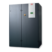
Specifies the primary application of the chiller unit for indoor cooling.
Overview of the unit's internal components, controller, and operational conception.
Details on the refrigeration system, including components and safety devices.
Description of the chilled water circuit components and their functions.
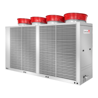
Explanation of the cooling medium circuit for G and GE versions.
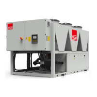
Description of DX, Mix, and FC operating modes for GE units.
Legend for symbols used in refrigeration and water circuit diagrams.
Schematic diagram of the cooling system for version A.
Schematic diagram of the cooling system for version G.
Schematic diagram of the cooling system for version GE.
Specifies operating conditions for temperature, humidity, and pressure.
Detailed technical specifications for CSI A/G unit types.
Detailed technical specifications for CSI GE unit types.
Graphical representation of unit dimensions and cabinet sizes.
Guidelines for choosing a suitable and safe location for chiller installation.
Instructions for safely moving and positioning the chiller unit.
Procedures for connecting refrigerant and water piping systems.
Design and connection details for the refrigerant piping.
Guidelines for connecting the chilled water and cooling medium piping.
Steps and safety precautions for making the electrical connections.
Procedure for charging the refrigerant circuit with refrigerant.
Instructions for filling the chilled water and cooling medium circuits.
Steps for filling and bleeding the chilled water circuit.
Procedure for filling and bleeding the cooling medium circuit, including anti-freeze.
Steps for checking and controlling the electrical box components.
Safety precautions to be followed during maintenance work.
Schedule for routine maintenance tasks on various components.
Procedures for checking refrigerant charge, quantity, and purity.
Checks for water circuit tightness and condenser condition.
Safety warnings and checks for electrical box and unit interior.
Table detailing alarm messages, their causes, and elimination steps.
Description and mounting instructions for the raised floor stand option.
Details on optional crank case heater and hotgas bypass for the refrigerant circuit.
Description of optional pumps and valves for the chilled water circuit.
Information on control valves for the cooling medium circuit.
Details on the optional C7000 Advanced terminal for chiller control.