58
OPTION
EN/09.2017/G44 © STULZ GmbH – all rights reserved
cybercool indoor chiller original instructions
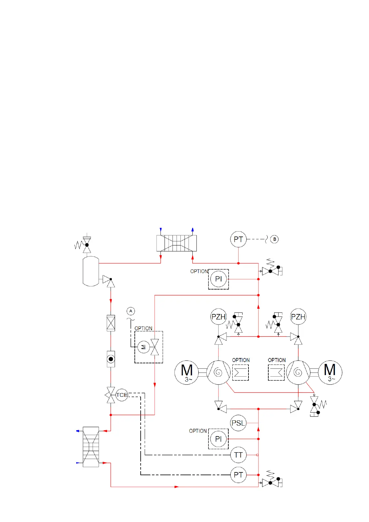
Refrigerant circuit of a GE unit
Chilledwater
circuit
Primarycircuit
Evaporator
Condenser
Coolingmediumcircuit
Secondary circuit
Crankcaseheater
HGBPvalve
11.2 Refrigerant circuit
Crank case heater
Aroundthecrankcaseofthecompressor,anelectricalheaterisinstalled,whichisinoperation,whenthe
compressorisswitchedoff,toassuretheconstantoillubricityatthecompressorstartwithlowambienttem-
peratures. The power depends on the compressor size from 34 W to 150 W.
Pressure gauge in the refrigerating circuit
to indicate the suction pressure and/or the condensation pressure
Hotgas Bypass, electronically controlled (for GE units only)
The unit can be eqipped with an electronically controlled hotgas bypass for the proportional capacity control
in the range of 40 to 100% of the nominal cooling capacity. The hotgas bypass valve is commanded and pro-
portionallycontrolledbytheC7000controller.
A part of the hotgas bypasses the condenser by the hotgas bypass line and is fed upstream the evaporator.
This lets the evaporation temperature rise whereas the cooling capacity sinks.