11
A
HD-Patronendruckschalter ACB 36-29bar
M74360
HD-Patronendruckschalter ACB 36-29bar
M74360
ND-Schalter
Patronendruckschalter-ACB-3-6bar
M74358
Schauglas Parker SA-17s
1103757
Filtertrockner DML 417s
1106182
Membrandruckausdehnungsgefäß 8l 2,5bar
M53268
Frostschutzthermostat TR-1-F-U
M26386
Expansionsventil E3V65SSS10
1104804
A (1 : 5)
ND-Schalter
Patronendruckschalter-ACB-3-6bar
M74358
© STULZ GmbH – all rights reserved EN/09.2017/G44
cybercool indoor chiller original instructions
3.2 Intended use
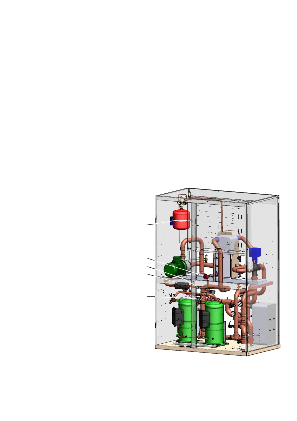
3.3 Design
In the upper half of the unit, the electric box is situated, which contains the controller C7000IOC, the main
switch and the electric components to control and monitor the chiller. All the wiring comes together in the
electrical section and is connected here.
The chiller unit control is effected by the on board I/O controller. The operational conception is designed such
as to allow to control up to 19 units from one unit. These units can be installed separately with a maximum
control line length of 1000 m.
With a cooling capacity of 60 kW and more, the unit is equipped with two compressors connected in parallel.
Units of version GE always contain two compressors.
Unit of version GE
electron. expansion valve
Sightglass
Filter dryer
HP switch
Expansion tank in the chilled water circuit
(Secondary circuit)
This chiller unit is used to cool water for technical units and A/C units within the application limits stated in
chapter 4.1. The chiller is designed for indoor installation. Any use beyond this is not deemed to be use as
intended.