31
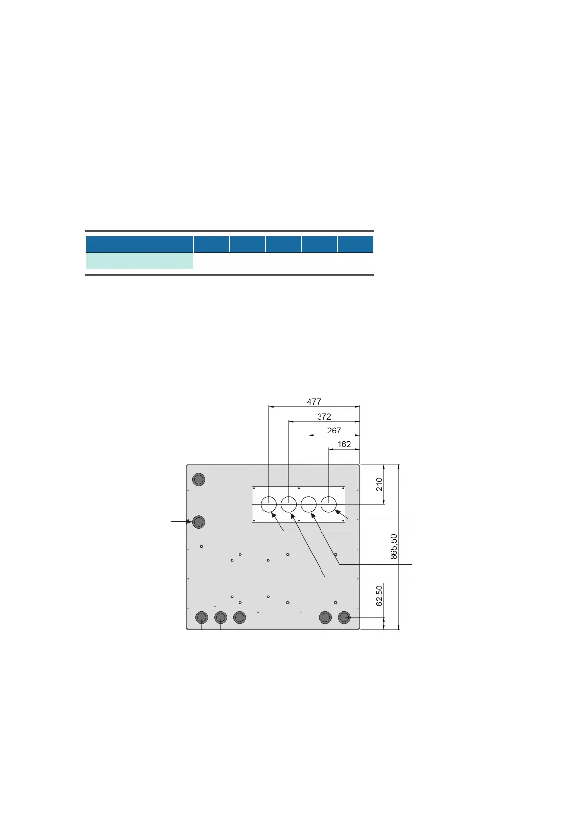
Gerät 221 421 661 841 981
Ein-/Austritt 28 42 54 54 54
© STULZ GmbH – all rights reserved EN/09.2017/G44
cybercool indoor chiller original instructions
Connecting the chiller to the external system
• read the diameter of the chilled water lines out of the table, to establish the lines between the external sys-
tem and the chiller.
• take the position of the connections out of the drawings stated below, to conduct the lines to the unit.
• introduce the chilled water lines from the bottom into the chiller.
The water connections are executed in the shape of a screw connection with a soldering connection.
• Solder the part with the external thread of the connection to the external pipes.
5.3.2.1 Position of the water piping connections for version A/G
Unit rear side
Top view
Cooling water outlet
Cooling water inlet
(G-units)
Chilled water inlet
Chilled water outlet
safety valve drain
Connection diameter of the chilled water lines in mm
Unit
Inlet/outlet