Automatic Transmission
ELECTROHYDRAULIC CONTROL SYSTEM
AT-10
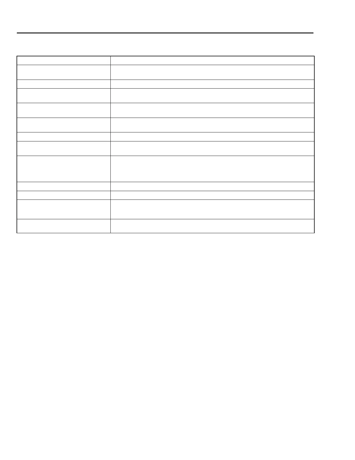
C: OUTPUT SIGNALS
Signal name Function
Shift solenoid 1, 2 Each of these signals controls shift step by turning the corresponding solenoid ON/OFF.
Activating timing is controlled for each solenoid to reduce shift shock.
Line pressure duty solenoid Regulates the line pressure according to driving conditions.
Lock-up duty solenoid Regulates the hydraulic pressure of the lock-up clutch to operate it in three modes
(open, smooth and lock-up).
Transfer duty solenoid Regulates the hydraulic pressure of the transfer clutch to control the driving force to the
rear drive shaft.
AT OIL TEMP light Causes the light to illuminate when ATF becomes excessively hot (exceeds a set tem-
perature level).
2-4 brake duty solenoid Regulates 2-4 brake operating pressure to reduce shifting shocks.
2-4 brake timing solenoid Switches on or off the pressure acting on 2-4 brake timing valve B to control the release
timing of the 2-4 brake.
Low clutch timing solenoid Switches on or off the pressure acting on the low clutch timing valve B to control the re-
lease timing of the low clutch.
Also switches on or off the pressure acting on the reverse inhibit valve to control the re-
verse inhibit function.
Torque control signal 1 Reduces engine torque during range selection and gear change.
Torque control signal 2 Reduces engine torque during range selection and gear change.
POWER indicator light Indicates whether the shift pattern is “Base” or “Power”. The indicator lights in the
POWER mode. This light is also used to display diagnostic trouble codes for the on-
board diagnosis function.
HOLD indicator light Indicates whether the shift pattern is “Base” or “Hold”. The indicator lights in the HOLD
mode.
 Loading...