1-8
1. Introduction|Structure
1.Introduction
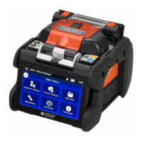
■Input/output panel
5
SD card slot
SELECT switch
DC output terminal
DC input terminal
2
4 3
1
USB port
Used to download stored splice
loss data when connected to a
PC.
DC input terminal
Input power via AC adapter.
SD card slot
For splice data output.
Insert Wireless LAN SD card in
this slot when usin
SumiCloud™.
DC output terminal
Used to supply DC power to a hot
jacket remover.
SELECT switch
Displays Splice/Heater program
selection screen. (▸See below)
1
2
3
4
5
・To ensure drip-proof and dust-proof performances, close input/output panel
securely.
・Do not press the keys on the keypad with a sharp ob
ect (e.
. a ballpoint pen,
screwdriver, or nail) Doing so will damage the keypad.
USB port