5-12 Sun StorEdge 3000 Family FRU Installation Guide • May 2004
Note – To ensure that a thumbscrew is finger-tight, tighten it with a screwdriver
and then loosen the thumbscrew counterclockwise a quarter-turn.
When you power on your array, if you hear an audible alarm and see a blinking
amber Event light on the front of your array, the SES firmware or its associated PLD
code in the new controller has a version that is different from the code in the other
I/O controller in your array. To solve this mismatch, refer to “SES Firmware Update
Sometimes Required with I/O Controller Module Replacements” on page 5-8.
Note – The beep code that identifies an SES or PLD firmware mismatch is the
repeating Morse code letter “R,” dot dash dot.
5.3 Installing Small Form-Factor Pluggable
Transceivers
Fibre Channel arrays use small form-factor (SFP) transceivers to attach the array to
hosts and expansion units.
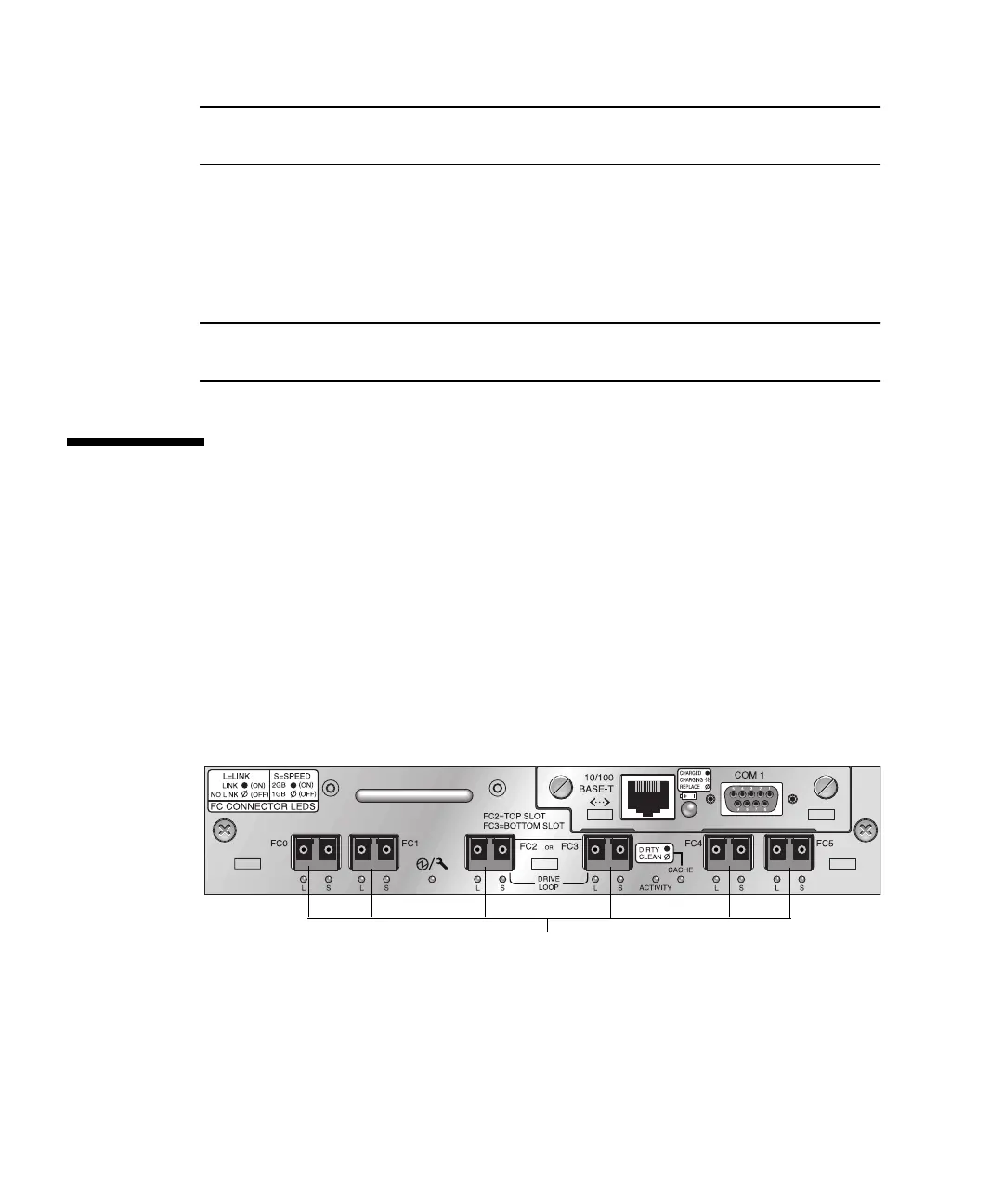
Sun StorEdge 3510 FC array I/O controller modules have six SFP ports, as shown in
the lower row of ports in
FIGURE 5-3. These ports are labeled FC0 through FC5. Sun
StorEdge 3511 FC array I/O controller modules have eight SFP ports, as shown in
FIGURE 5-4. SFP ports on the Sun StorEdge 3511 FC array are also labeled FC0
through FC5.
FIGURE 5-3 Six SFP Ports on a Sun StorEdge 3510 FC Array I/O Controller Module
SFP ports
 Loading...


