8
Configuration Table
No. Model Base
Battery
module
Top cover Switch gear
Side cover
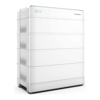
1 SBR096 1 3 1 1
-
2 SBR128 1 4 1 1 1
3 SBR160 1 5 1 1 2
4 SBR192 1 6 1 1 3
5 SBR224 1 7 1 1 4
6 SBR256 1 8 1 1 5
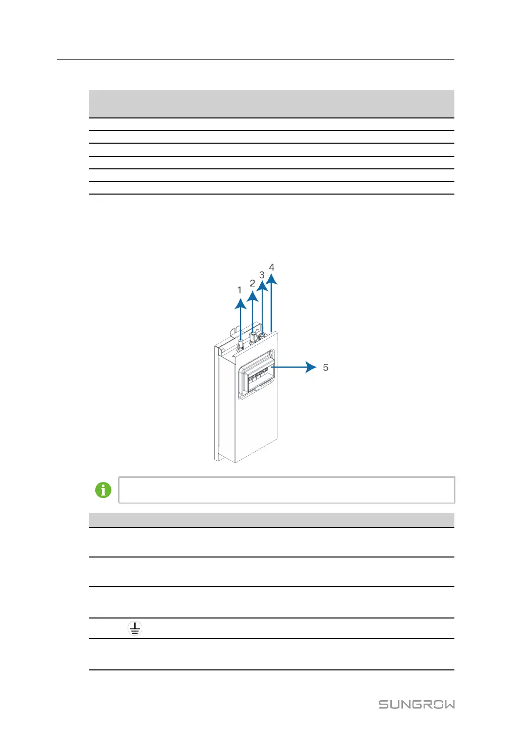
2.2 Terminal Description
All electrical terminals are located at the switch gear.
Images are for reference only. The actual products received may differ.
No. Label
Description
1 P-
The system negative terminal, connected to the PCS nega-
tive terminal
2 P+
The system positive terminal, connected to the PCS positive
terminal
3 COMM
To enable the communication between the PCS and the
battery
4
Grounding terminal, connected to the ground
5
DC circuit
breaker
To connect/disconnect the DC circuit, for power-on, power-off,
and short-circuit protection
2 Product Description User Manual