34
step 3 Lead the cable through cable gland, and insert the crimp contact into the insulator until it
snaps into place. Gently pull the cable backward to ensure firm connection. Tighten the ca-
ble gland and the insulator (torque 2.5 N.m to 3 N.m).
step 4 Check for polarity correctness.
- - End
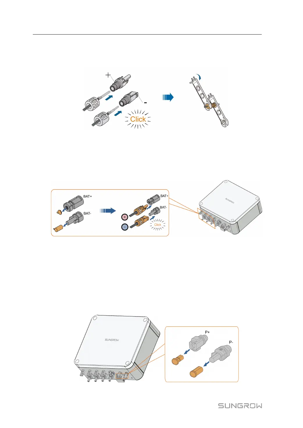
5.6.2 Installing the Battery Connectors
step 1 Connect the Battery connectors to corresponding terminals until there is an audible click.
step 2 Seal the unused Battery terminals with the terminal caps.
- - End
5.7 SUNCLIX Connection
step 1 For the assembly of the SUNCLIX connector, refer to the section"4.7 Assembling the SUN-
CLIX Connector".
step 2 Remove the waterproof lid from P+ and P– the terminal.
step 3 Plug the connectors into P+ and P– terminals.
5 Parallel System(Optional) User Manual