Do you have a question about the Sungrow SBR096 and is the answer not in the manual?
Covers trademarks, software licenses, and usage restrictions.
Details the manual's purpose, validity, target audience, and usage guidance.
Explains the meaning of hazard symbols like DANGER and provides general safety notes.
Defines DANGER, WARNING, CAUTION, and NOTICE symbols for risk assessment.
Lists common abbreviations used throughout the manual, such as BMS, LFP, PCS.
General safety instructions for working with the battery, highlighting potential risks.
Provides guidelines for safe handling, warranty considerations, and proper usage.
Details procedures for emergency situations like leaking batteries and fires.
Instructions for dealing with leaking batteries, including first aid and contact procedures.
Procedures and precautions for fighting battery fires, including protective equipment.
Steps to take if a battery is submerged in water or flooded.
Guidance on handling damaged batteries and potential hazards.
Warns that damaged batteries may release hazardous material and flammable gas.
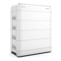
Overview of the high-voltage LFP battery system for residential use.
Details product design, LED indicators, and nameplate information.
Illustrates and names the main physical components of the battery module.
Lists configuration details for different battery models (SBR096 to SBR256).
Identifies and describes the function of each electrical terminal on the switch gear.
Explains various symbols found on the product, including danger, flame, shock, and disposal warnings.
Describes the SOC and Status indicators and their meanings.
Details the states (ON, Slow blink, Fast blink) for Blue and Red LED indicators.
Explains how to power the battery on and off using the status indicator button.
Instructions for inspecting the device after delivery for any damage or missing parts.
Lists all items included in the product package, with quantities.
Provides guidance on proper storage conditions, temperature, humidity, and duration.
Highlights safety warnings for professional installation and adherence to standards.
Specifies criteria for selecting an optimal mounting location for the battery.
Details environmental conditions required for installation, including materials and accessibility.
Specifies required clearances around the battery for ventilation and access.
Lists essential tools needed for mounting the battery, including safety gear.
Provides an exhaustive list of tools for installation, including cutting, measuring, and fastening tools.
Details the requirements and steps for preparing the PE (grounding) cable.
Step-by-step guide for assembling the SUNCLIX connector onto the cable.
Details the process of stripping cable, inserting components, and tightening the connector.
Instructions for assembling the optional communication connector.
Step-by-step instructions for installing an RJ45 plug into a front plug connector.
Instructions for attaching the feet to the battery base for mounting.
Steps for positioning the base and marking drilling points on the wall.
Guidance on drilling holes and installing expansion sleeves for wall mounting.
Instructions for placing the base at the required distance and securing it.
Steps for placing battery modules onto the base and securing them.
Instructions for connecting the switch gear to the base.
Details on fixing the switch gear using screws or studs, varying by top cover type.
Instructions for securing the mounted battery assembly to the wall using brackets.
Steps for connecting the switch gear and securing the battery to the wall with brackets.
Instructions for connecting communication cables G1 and G2.
Details on securing the switch gear with M5 screws or studs for different top cover configurations.
Instructions for fixing the battery to the wall using bracket E1 or E2.
Instructions for connecting the PE (grounding) cable to the terminal.
Steps for stripping and crimping DC cables for battery connectors.
Instructions for connecting the assembled battery connectors to the terminals and sealing unused ones.
Guide to connecting the SUNCLIX connector to the P+ and P- terminals.
Lists the components included for setting up a parallel battery system.
Lists items like combiner box, brackets, connectors, and terminals for parallel systems.
Step-by-step guide for mounting the combiner box onto its bracket on the wall.
Illustrates and describes the terminals on the bottom of the combiner box.
Details the labels and connections for COM terminals (BMS/CAN, RS485).
Explains the function of terminals like BAT+, BAT-, COM, P+, P-, and PE on the combiner box.
Provides a table detailing the labels for COM2 terminals.
Illustrates how up to four batteries can be connected in parallel.
Explains how to connect COMM terminals of batteries to the combiner box using CAN cables.
Details the connection of the grounding terminal of the combiner box to the PE terminal.
Instructions for connecting the PE (grounding) cable to the terminal.
Steps for stripping and crimping DC cables for battery connectors.
Instructions for connecting the assembled battery connectors to the terminals and sealing unused ones.
Guide to connecting the SUNCLIX connector to the P+ and P- terminals.
Step-by-step guide for assembling the COM2 cable connector, including stripping and crimping.
Instructions for stripping the cable and crimping cord end terminals for COM2 connection.
Guide for plugging wires into the terminal block according to device labels.
Instructions for fastening the swivel nut on the COM2 connector.
Steps for removing the lid, inserting the connector, and confirming the connection.
Refers to assembly of optional communication connector for COM1.
Instructions for inserting the COM1 connector into the combiner box terminal.
Checklist of items to verify before starting the commissioning process.
Steps to follow to start up the battery system for the first time.
Procedure for connecting AC/DC sides, checking battery status indicator (blue light).
Details on how the system handles initial power-up and status indication.
Instruction to close the protective cover after commissioning steps.
Warning regarding short-circuit faults during commissioning and contacting SUNGROW for repair.
Describes the automatic calibration process after initial power-on.
Procedure for safely decommissioning the battery from the system.
Advises contacting SUNGROW for disposal and warns about replacement procedures.
Information on viewing fault codes and troubleshooting methods via App or LCD screen.
Lists alarm IDs and corrective measures for battery faults like voltage and temperature issues.
Provides corrective actions for battery alarms related to ambient temperature.
Details inspection items for annual maintenance, including module status, cleanliness, and wiring.
Outlines inspection tasks for maintenance performed every six months.
Checks for battery module damage, noise, temperature, humidity, and dust.
Inspection of warning signs, wiring, PCS connections, and corrosion.
Presents technical parameters for high voltage LFP batteries (SBR096/SBR128/SBR160).
Details technical parameters for SBR192, SBR224, and SBR256 battery models.
Lists technical parameters for the SJR-04 battery combiner box.
Details the warranty terms, conditions, and evidence required for service.
Lists circumstances under which SUNGROW may refuse warranty claims.
Provides contact details for SUNGROW support in various regions for product inquiries.
Lists specific contact information for SUNGROW offices in Germany, Greece, India, Italy, Japan, Korea, Malaysia, Philippines, Spain, Turkey.
Provides contact information for SUNGROW in Vietnam, Poland, and Benelux countries.
| Brand | Sungrow |
|---|---|
| Model | SBR096 |
| Category | Camera Accessories |
| Language | English |