32
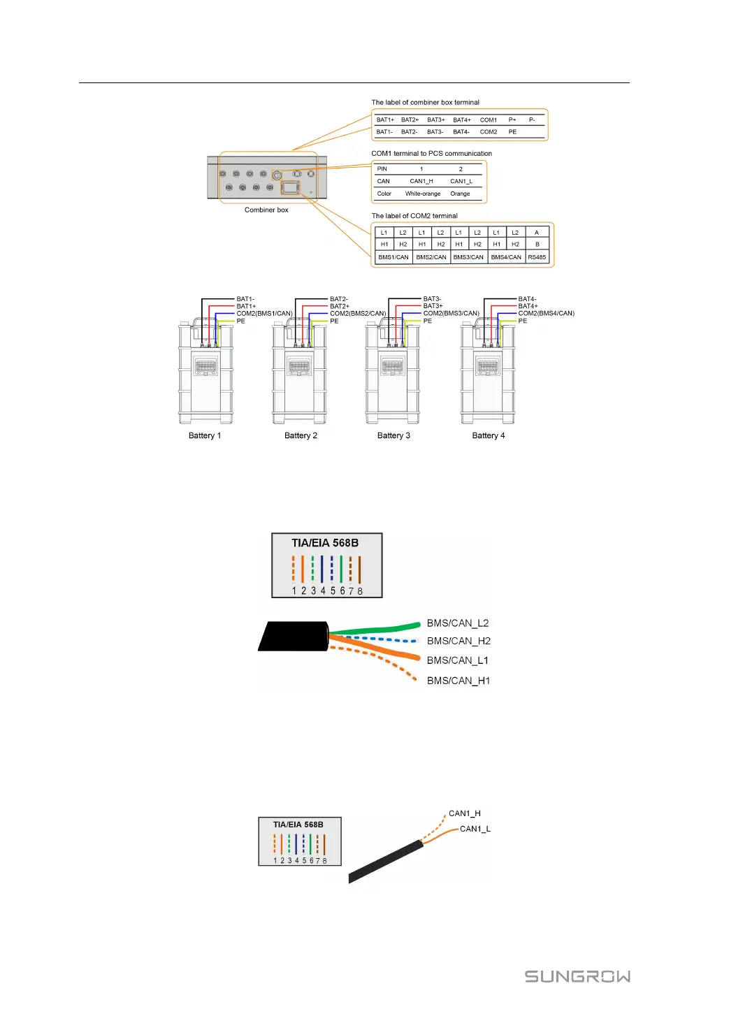
• The COMM terminal of the battery is connected to the COM2 terminal of the combiner
box. Signal cable 1 white and orange cable is used as BMS/CAN_H1; signal cable 2 or-
ange cable is used as BMS/CAN_L1; signal cable 5 white and blue cable is used as
BMS/CAN_H2; and signal cable 6 green cable is used as BMS/CAN_L2.
• The grounding terminal of the battery is connected to the PE terminal of the combiner
box.
• The COM1 terminal of the combiner box is connected to the PCS. Signal cable 1 white
and orange cable is used as CAN1_H; and signal cable 2 orange cable is used as
CAN1_L.
5 Parallel System(Optional) User Manual