26
The installation method of communication connector G1 and communication con-
nector G2 is the same, and here takes G1 as an example.
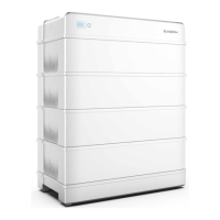
For communication between the battery and the PCS. Connect the communication cable
from the “COMM” terminal of the battery to the PCS. Strip the insulation layer of the commu-
nication cable with a wire stripper, and lead the corresponding CAN1_H/CAN1_L signal ca-
ble out. Cut off the redundant signal cable and warp it with a heat-shrink tubing. Signal cable
1 white and orange cable is used as CAN1_H; and signal cable 2 orange cable is used as
CAN1_L.
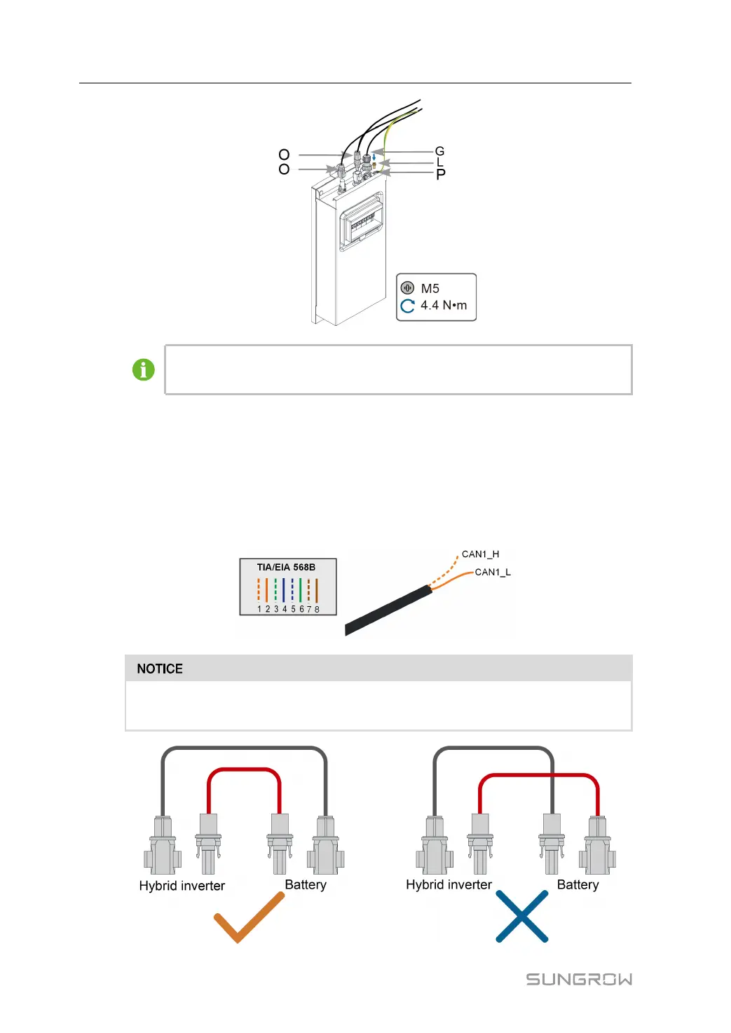
Please ensure that the SUNCLIX cable are connected to same terminals, as shown
below.
4 Mounting User Manual