44
• Measure the electrical conductivity between the device ground terminals and the total
equipotential connection copper bar to ensure the effectiveness of the internal ground
connection;
• Ground the shielding layers and protection layers of the cables connected to the PCS
outside.
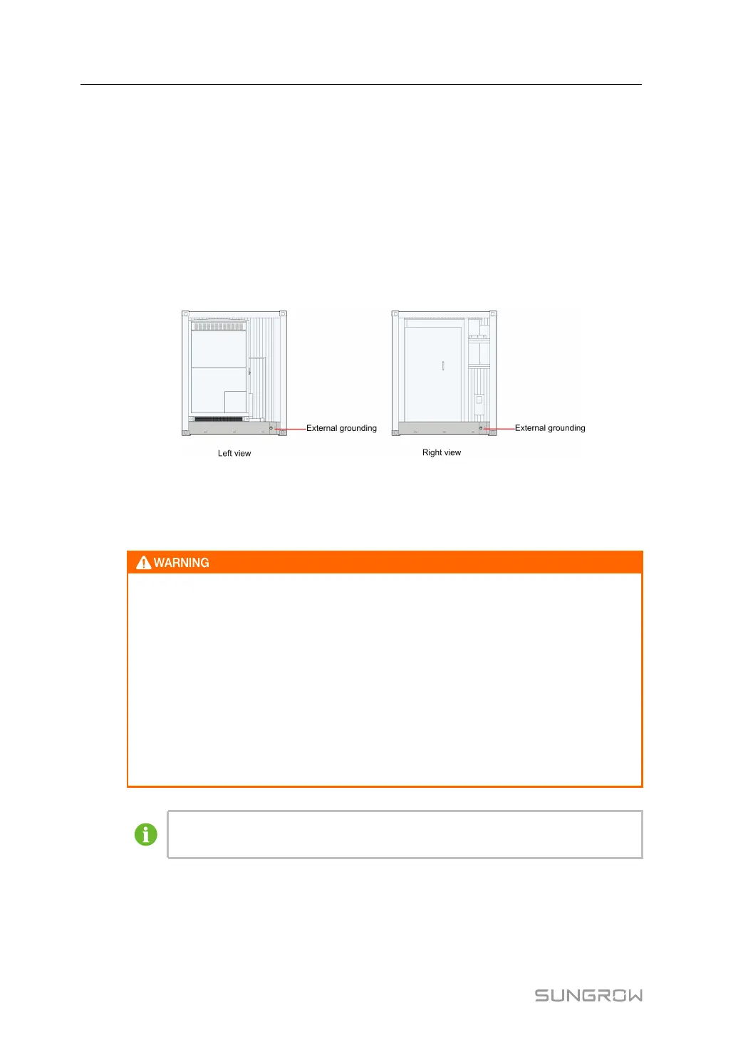
6.6.3 External Grounding
The PCS external ground point is located at the lower right corner on both sides of the PCS
with the hole specification of ϕ13. The positions are shown in the figure below. It is recom-
mended to use M10 bolt with a torque of 34 - 40(N•m) / 301 - 354(lbs•in).
figure 6-6 Positions of the external grounding points
Perform the external grounding according to the on-site situation and the instructions of the
plant staff. The grounding resistance should be no more than 4Ω.
The on-site PE cable shall be connected to the external grounding terminal of the
PCS cabinet. It is strictly prohibited to connect it to the grounding bar inside the
PCS cabinet!
The external grounding terminal of the PCS cabinet is covered with a protective
sticker, which must be torn off before on-site ground connection. Otherwise, the
ground connection is inadequate and will affect system performance.
Devices inside the PCS cabinet have been connected to the internal floating equi-
potential grounding copper bar. The installation hole in the floating grounding cop-
per bar is reserved for the power cable connection, and no on-site PE cable can be
connected to it.
The grounding resistance should be obtained from local standards and
regulations.
6 Electrical Connection System Manual
 Loading...