55
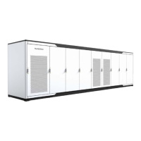
Devices inside the PCS cabinet have been connected to the internal floating equi-
potential grounding copper bar. The installation hole in the floating grounding cop-
per bar is reserved for the power cable connection, and no on-site PE cable can be
connected to it.
The on-site PE cable shall be connected to the external grounding terminal of the
PCS cabinet. It is strictly prohibited to connect it to the grounding bar inside the
PCS cabinet!
7.3.2 Checking PCS
• Ensure that the DC and AC switches are in the “OFF” position.
• Check and ensure the switches of the PCS and upstream and downstream devices meet
the requirements and work normally.
7.3.3 Checking Batteries
Make sure the measuring devices are connected and used correctly. There will be
electric arc if otherwise.
DC side voltage should not exceed the PCS maximum allowable DC input voltage.
Too high DC voltage may damage the PCS, and even cause safety incidents.
Ensure the polarity correctness. If otherwise, serious consequence may follow.
Check the storage battery before starting the device to make sure the max voltage of the
battery meets the requirement.
• Record field measured data accurately;
• Make sure the positive and negative polarities are correct. Incorrect polarity may damage
the module seriously.
• Measure the resistance of cables (between the terminal box and the PCS) by ohmmeter.
Accurately record all measured data.
7.3.4 Checking Grid Voltage
• Measure accurately the grid 3-phase line-to-line voltage: L1-L2, L1-L3, and L2-L3. The
measured data should not exceed the grid permissible value and the three-phase vol-
tages should be balance.
Adjust the transfer ratio of the transformer by qualified personnel if the grid
voltage deviation is serious.
System Manual 7 Commissioning

 Loading...


