46
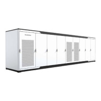
figure 6-7 DC side terminals of single branch version (SC2400UD-MV-US/SC2750UD-MV-US/
SC3150UD-MV-US/SC3450UD-MV-US/SC4000UD-MV-US/SC5000UD-MV-US)
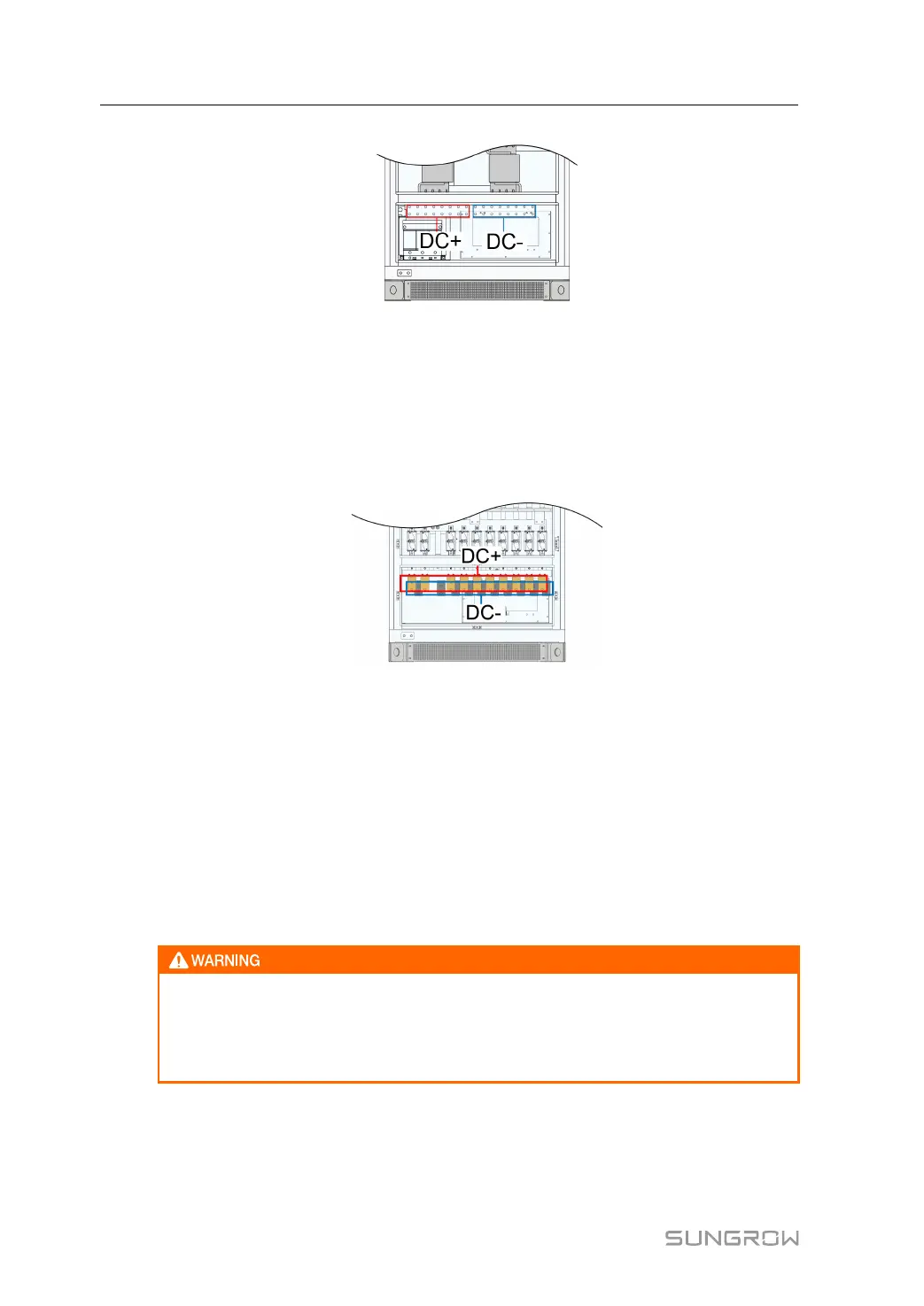
For multi-branch PCS, the number of branches varies from model to model. SC2400_2750_
3150_3450UD-MV-US supports up to 12 branches and SC4000_5000UD-MV-US supports
up to 10 branches, as shown in the figure below.
figure 6-8 DC side terminals of multi-branch version (SC4000UD-MV-US/SC5000UD-MV-US)
Proceed as follows to connect the DC cables:
step 1 Make sure the output circuit breakers of upstream combiner boxes are disconnected;
step 2 Connect the cable that has been crimped beforehand;
1 Select bolts matching the cable lug, recommended specification: M12×50.
2 Attach the cable lug to the DC connection copper bar following the double-hole cable
connection sequence of copper wire and aluminum wire.
3 Fasten the bolts with a screwdriver or a spanner with recommended torque.
• Incorrect connection sequence may cause fire. Please pay maximum attention
to the connection sequence.
• Ensure the firmness of the cable connection. Poor connection or oxidation of
the surface may cause over-heating or fire.
6 Electrical Connection System Manual
 Loading...