User Manual 5 Electrical Connection
27
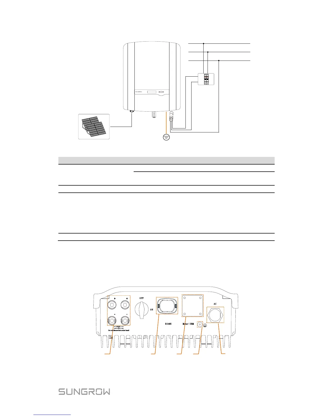
Fig. 5-1 Electrical Connection Diagram
-S series: one pair of PV terminals.
-D series: three pairs for SG8K3-D and two pairs
for other –D inverters.
Used as a protective device during electrical
connection. User equips this device according to
the maximum output voltage and current.
The PE wire of the AC terminal must be directly
connected to the grounding bar. Do not connect it to
protection devices such as the circuit breaker.
220 Vac / 230Vac / 240 Vac.
5.1 Terminal Description
All electrical terminals are located at the bottom of the inverter.
Fig. 5-2 Terminal Description
 Loading...