10
Sunstone Welders User Manual: CDDP-A
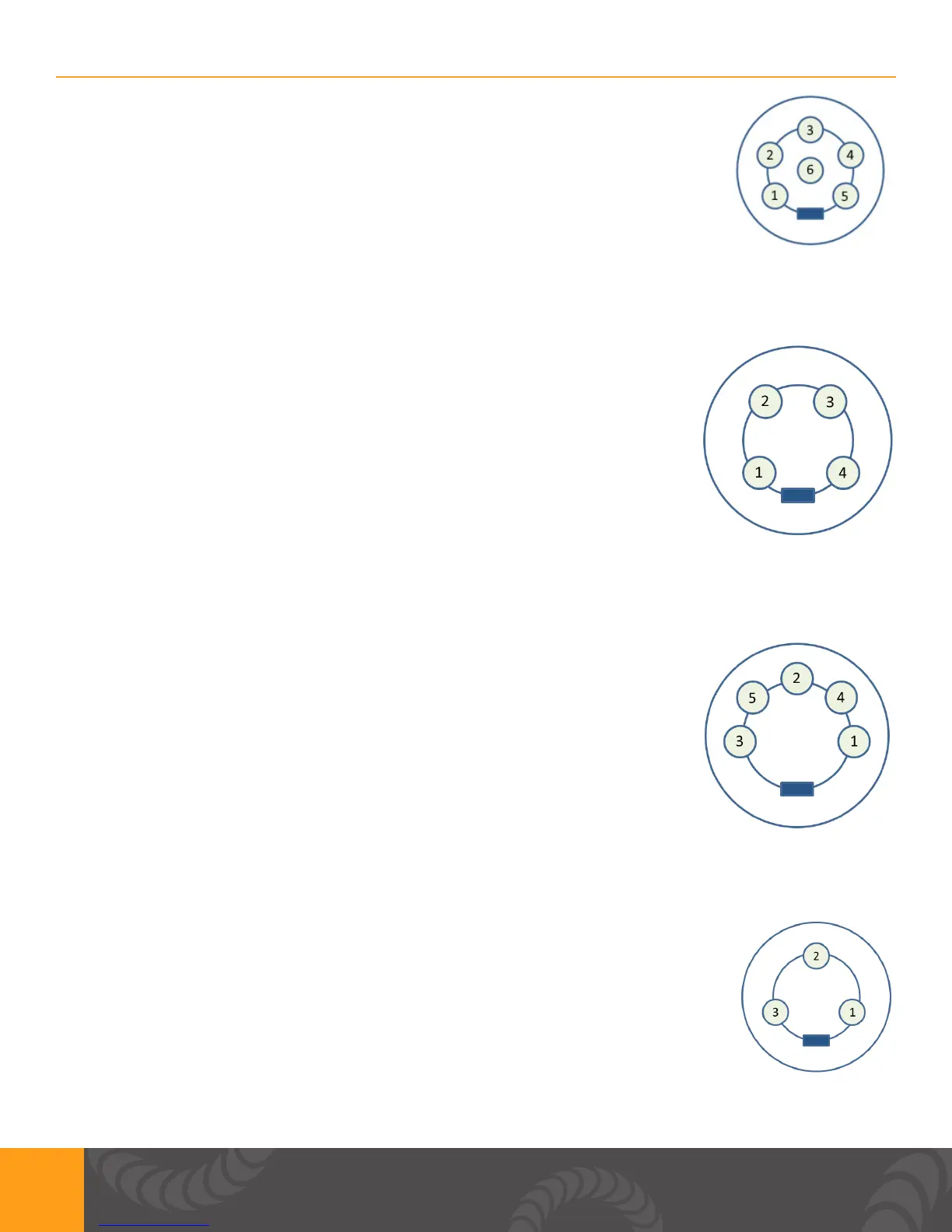
ESTOP: MATES TO SD60LP
Pin 1: GND/Shield
Pin 2 & 3: Normally open, ESTOP enabled. Close circuit to disable ESTOP
FIGURE 10: E-STOP Connector (SD-60LS)
WH CONTROL: MATES TO SD40LP
Pin 1: GND/Shield
Pin 2: Weld Head Actuation 2. +12VDC(0.5A Max) is sent when weld head
needs to actuate.
Pin 3: Weld Head Actuation 1. +12VDC(0.5A Max) is sent when weld head
needs to actuate.
Pin 4: GND/Shield
FIGURE 11: WH Control Connector (SD-40LS)
PRIMARY TRIGGER: MATES TO SD50LP
Pin 1: Variable Foot Pedal. Connect this to Pin5 (+12VDC) with a 10Kohm
potentiometer.
Pin 2: Primary Trigger. Connect this to pin3 (GND) when trigger is desired.
Pin 3: GND/Shield
Pin 4: Secondary Trigger. Connect this to pin3 (GND) when trigger is desired.
Pin 5: +12VDC limited.
FIGURE 12: Primary Trigger Connector (SD-50LS)
SECONDARY TRIGGER: MATES TO SD30LP
Pin 1: Not Connected
Pin 2: +12V
Pin 3: Secondary Trigger. Connect this to pin 2(+12VDC) when trigger is desired.
FIGURE 13: Secondary Trigger (SD-30LS)