15
the total welder energy storage and is also used to set the peak weld current. The pulse energies are
then adjusted to provide the appropriate weld energy released during each weld.
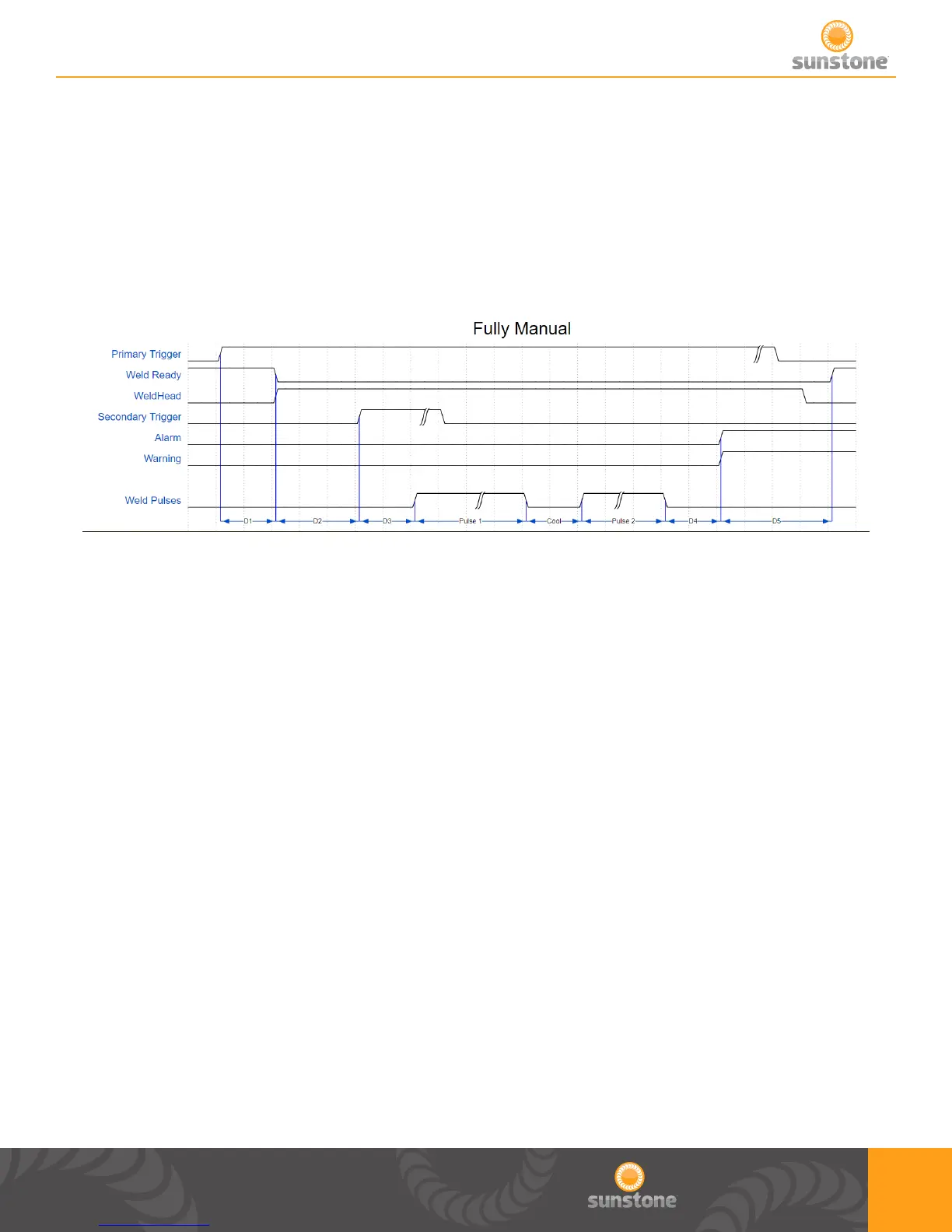
Timing Diagrams
D1: A delay that occurs from the time primary trigger is triggered and the signal to the weld head is
sent. Typical time for this is between 1 and 50 milliseconds.
D2: A delay that occurs from the time the weld head is engaged and when trigger 2 is triggered.
D3: A delay that occurs from the time the secondary trigger is triggered and the weld occurs. Typical
time for this is between 1 and 50 milliseconds.
Pulse 1: The duration of this delay is dependent on the energy programmed on welder for Pulse 1.
Cool: The duration of delay is dependent on the time programmed on welder for time between pulses.
User can select between 1 and 100 milliseconds. This time will be ignored if either pulse is disabled.
Pulse 2: The duration of this delay is dependent on the energy programmed on welder for Pulse 2.
D4: After this delay, alarms and warnings are sent. Typical time for this is between 1 and 50
milliseconds.
D5: After this delay the Weld Ready signal will return to a high position. This delay will depend on the
time needed to charge to the desired energy, but will typically be between 50 and 5000 milliseconds.