Batt Temp
Sensor
1 2 3 4 5 6 7 8 1 2 3 4 5 6 7 8
CT -L1
CT -L2
CT -L3
Gen start-up
N/O Relay
Parallel_A
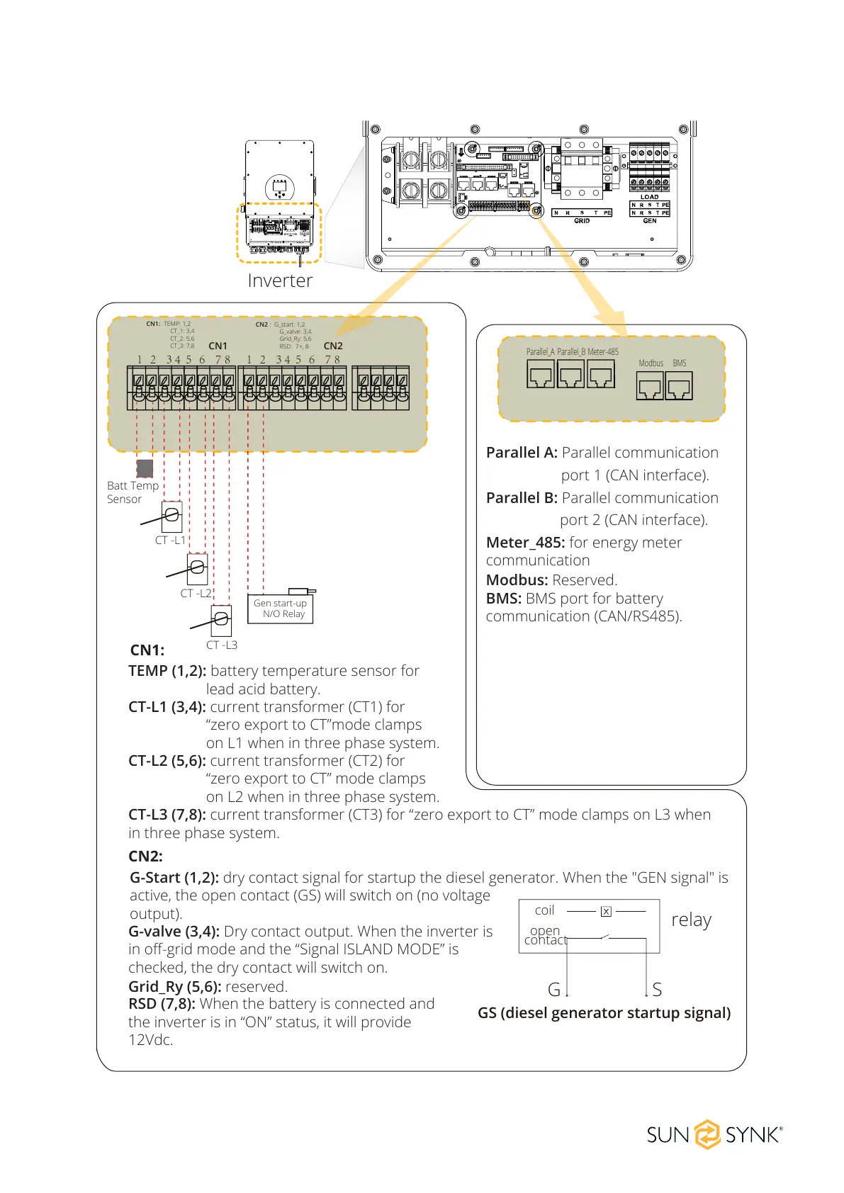
CN1: TEMP: 1,2
CT_1: 3,4
CT_2: 5,6
CT_3: 7,8
Parallel_B Meter-485
Modbus BMS
GS (diesel generator startup signal)
relay
coil
open
contact
G S
CN2 : G_start: 1,2
G_valve: 3,4
Grid_Ry: 5,6
RSD: 7+, 8-
CN1 CN2
Inverter
TEMP (1,2): battery temperature sensor for
lead acid battery.
CT-L1 (3,4): current transformer (CT1) for
“zero export to CT”mode clamps
on L1 when in three phase system.
CT-L2 (5,6): current transformer (CT2) for
“zero export to CT” mode clamps
on L2 when in three phase system.
CT-L3 (7,8): current transformer (CT3) for “zero export to CT” mode clamps on L3 when
in three phase system.
G-valve (3,4): Dry contact output. When the inverter is
in off-grid mode and the “Signal ISLAND MODE” is
checked, the dry contact will switch on.
Grid_Ry (5,6): reserved.
RSD (7,8): When the battery is connected and
the inverter is in “ON” status, it will provide
12Vdc.
CN1:
CN2:
G-Start (1,2): dry contact signal for startup the diesel generator. When the "GEN signal" is
active, the open contact (GS) will switch on (no voltage
output).
Parallel A: Parallel communication
port 1 (CAN interface).
Parallel B: Parallel communication
port 2 (CAN interface).
Meter_485: for energy meter
communication
Modbus: Reserved.
BMS: BMS port for battery
communication (CAN/RS485).