3 Installation
20
Grid connection
Extreme danger from electric shock!
· Touching live parts can result in death.
· All electrical work must be conducted by a quali-
fied electrician while observing the VDE regula-
tions, national and other regulations!
· Observe the pin assignment of the AC bayonet
connector. An incorrect assignment can result in
the device being destroyed.
· No consumers may be connected to the supply
line from the Solar Inverter to the mains fuse.
· Always separate the grid connection first by
switching off the corresponding mains fuse and
then the solar generator side by quickly opening
the DC load break switch.
If the voltage on the AC connection exceeds the
permissible value due to a long line length or an
insufficient cable cross-section, the Solar Inverter
will disconnected from the grid. In power grids with
a low output and a high solar generator output, this
can lead to individual Solar Inverters being switched
off and then on again several times.
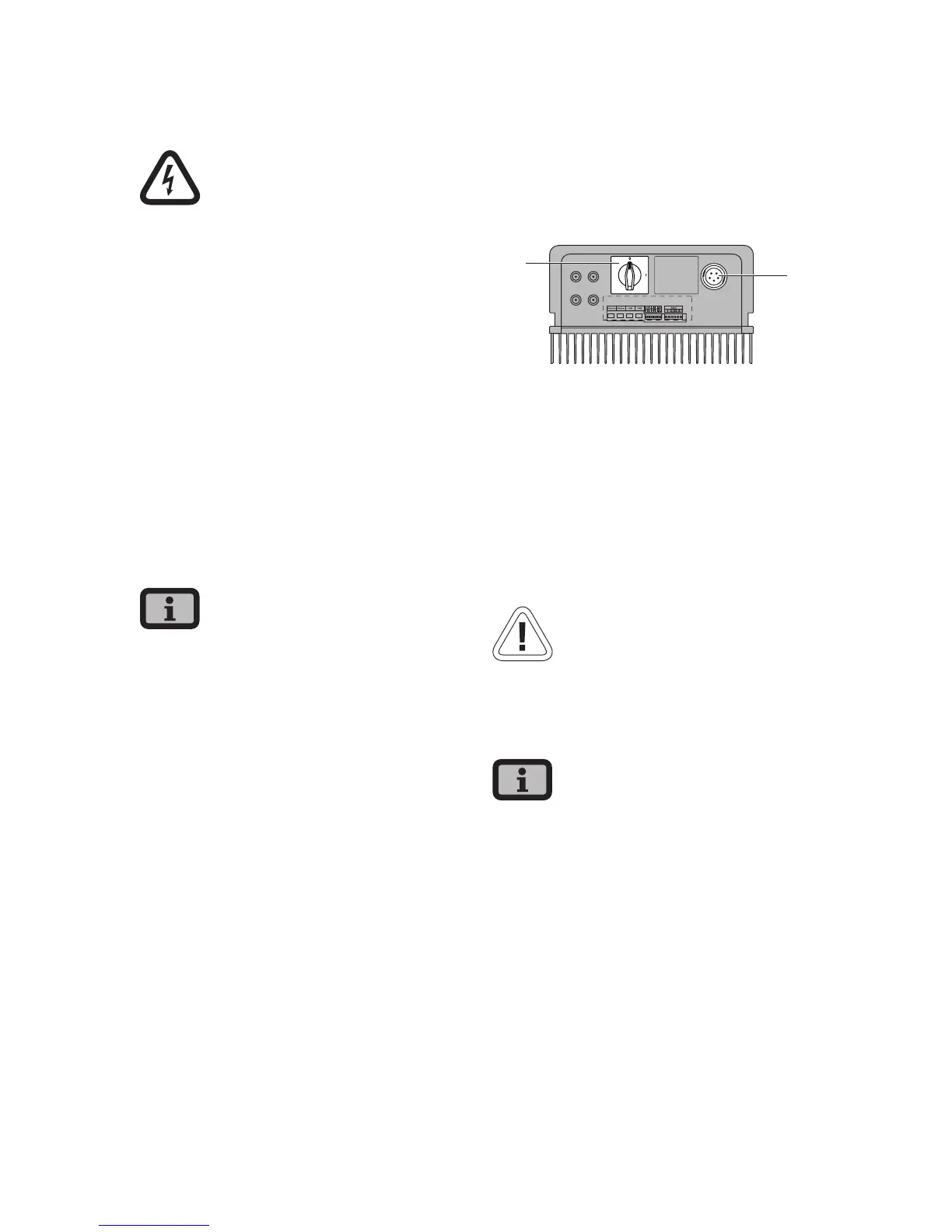
Survey
An AC bayonet connector on the underside of the
unit is used for the three-wire grid connection (L, N,
PE) of the Solar Inverter. The grid connection should
always be 1-phase. Feeding is single-phase via AC
terminal 2.
+–
+–
1
2
1 DC load break switch
2 AC connection
A basic distinction is made between two different
connection options of the Solar Inverter to the pub-
lic power grid:
· 3-phase AC grid (e.g. Germany)
· 1-phase AC grid (e.g. Italy, Spain)
CAUTION
· Observe the regional regulations for the grid
connection.
The Solar Inverter always only feeds via AC terminal
2. If several Solar Inverters are operated in parallel
in a 3-phase grid, AC terminal 2 of the device must
be distributed uniformly among the grid phases L1,
L2 and L3 to avoid unequal loading.