3 Installation
23
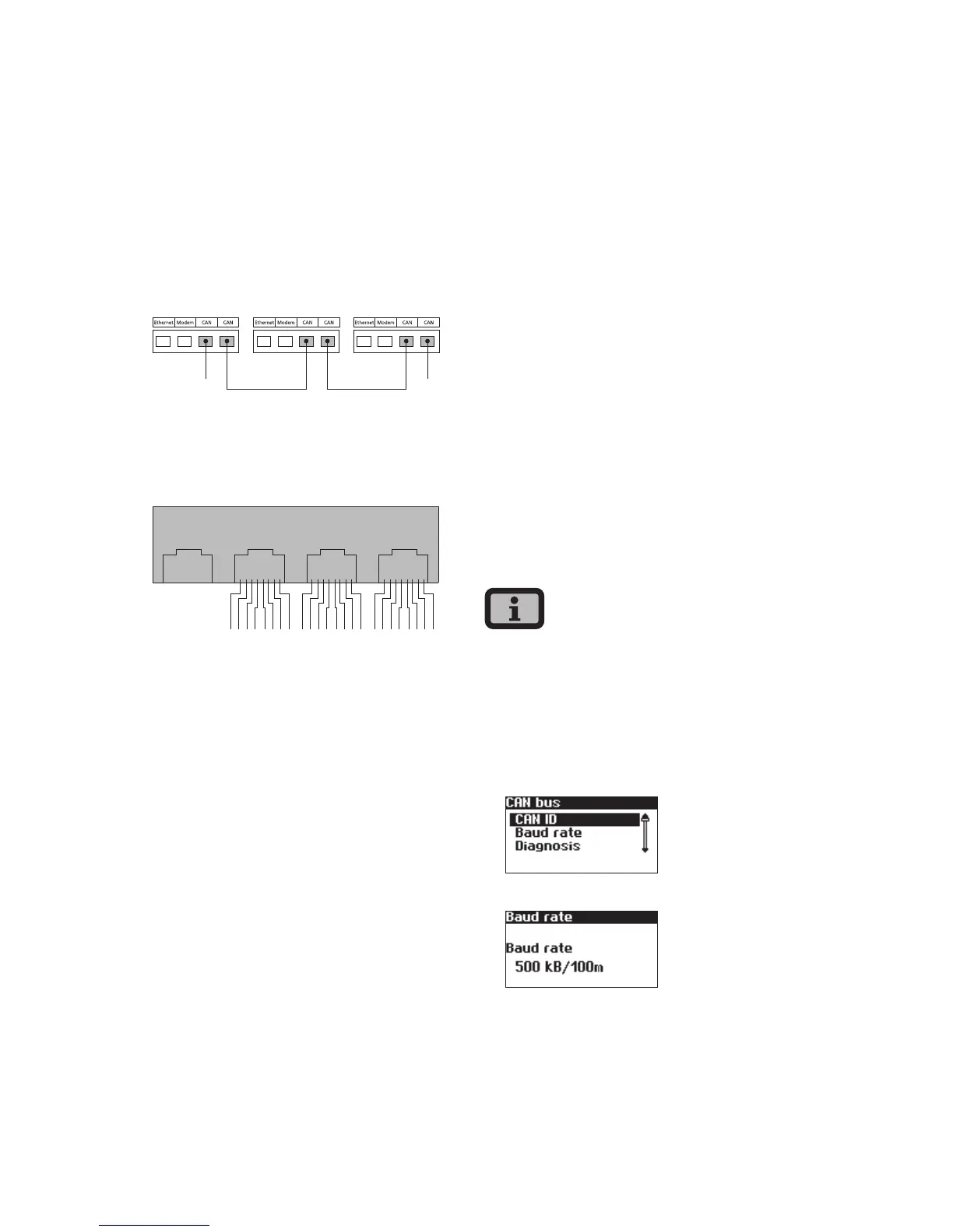
Networking Solar Inverters via CAN bus
Solar Inverters from the NT, AT und PT series can
be networked via the CAN bus interface. Use the
included Ethernet cable to network the Solar Invert-
ers with each other. Connect a terminating resistor
at the first and last Solar Inverter in the series. The
pluggable terminating resistors are included in the
delivery.
Device 1 Device 2 ...
1 1
1 Terminating resistor
Pin assignment
Ethernet Modem CAN CAN
2
134
6
578
2
134
6
578
2
134
6
578
The connectors for the CAN interfaces CAN IN and
CAN OUT and for the modem interface have the
following pin assignment
CAN
Pin ID Meaning
1 N.C.
2 CAN_GND 0 V / GND
3 CAN_H bus line (dominant high)
4 CAN_L_T termination
5 CAN_H_T termination
6 CANL bus line (dominant low)
7 CAN_SHLD optional CAN Shield
8 N.C.
Modem
Pin ID Meaning
1 >1 TXh
2 >2 TX1
3 <3 RXh
4 -4 VCC
5 -5 GND
6 <6 RXI
7 <7 R1h
8 <8 R1I
The total length of the CAN bus depends on the
selected bit rate. The following table shows the pos-
sible bit rates and the resulting bus lengths.
Bit rate Bus length
100 kbit/s 650 m
125 kbit/s 500 m
250 kbit/s 250 m
500 kbit/s 100 m
Solar Inverters of the PT series are delivered with a
default setting of 125 kbit/s. The default setting for
Solar Inverters of the NT and AT series is 500 kbit/s.
When Solar Inverters from different series are net-
worked the bit rate in all units must be identical.
The rate can be set via the Solar Inverter display or
the Sunways Browser.
Setting the bit rate via the display menu:
«Settings – Network – CAN Bus – Baud rate»