3 Installation
22
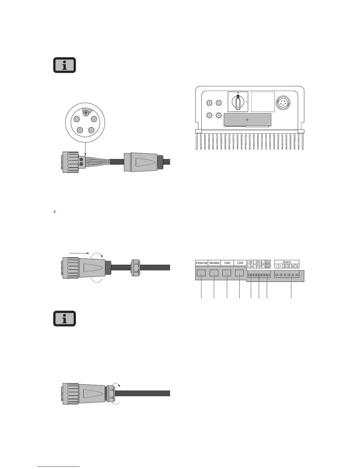
Pin assignment for AC bayonet connector
The diagram shows the connections inside the AC
connector, as indicated by the cut-out at the PE
connection.
1
2
4
3
1 = N
2 = L (feed-in phase)
3 = not used
4 = not used
= PE (protective earth conductor)
4. Screw plug housing to plug. To do this, press the
outer ring of the plug toward the plug housing.
Tightening torque: 1-2 Nm.
5. Tighten the cable gland.
Make sure the line is provided with a strain relief
device. When using cables with a diameter < 16 mm,
the line must be relieved just behind the connector.
Tightening torque for cable sheath diameters
from 13 to 20 mm = 6 to 8 Nm
3.3 Installing communication
The interfaces are located behind the weather-
proof connection box on the underside of the Solar
Inverter.
+–
+–
1
2
To open the connection box, loose the centre screw.
Then carefully pull way the box toward the front.
After you have installed the connection cable, close
the box again by guiding the locking hooks into the
notches in the housing and then pressing the box
onto the housing.
Retighten the mounting screw.
Interface overview
2
1 3 4 8765
1 Ethernet connection
2 Modem connection
3 CAN IN
4 CAN OUT
5 S0 interface (pulse output, e.g. for large display)
6 Connection for temperature and irradiation
sensor
7 RS485 interface
8 Connection for alarm relay