Temperature recorder and printer
8
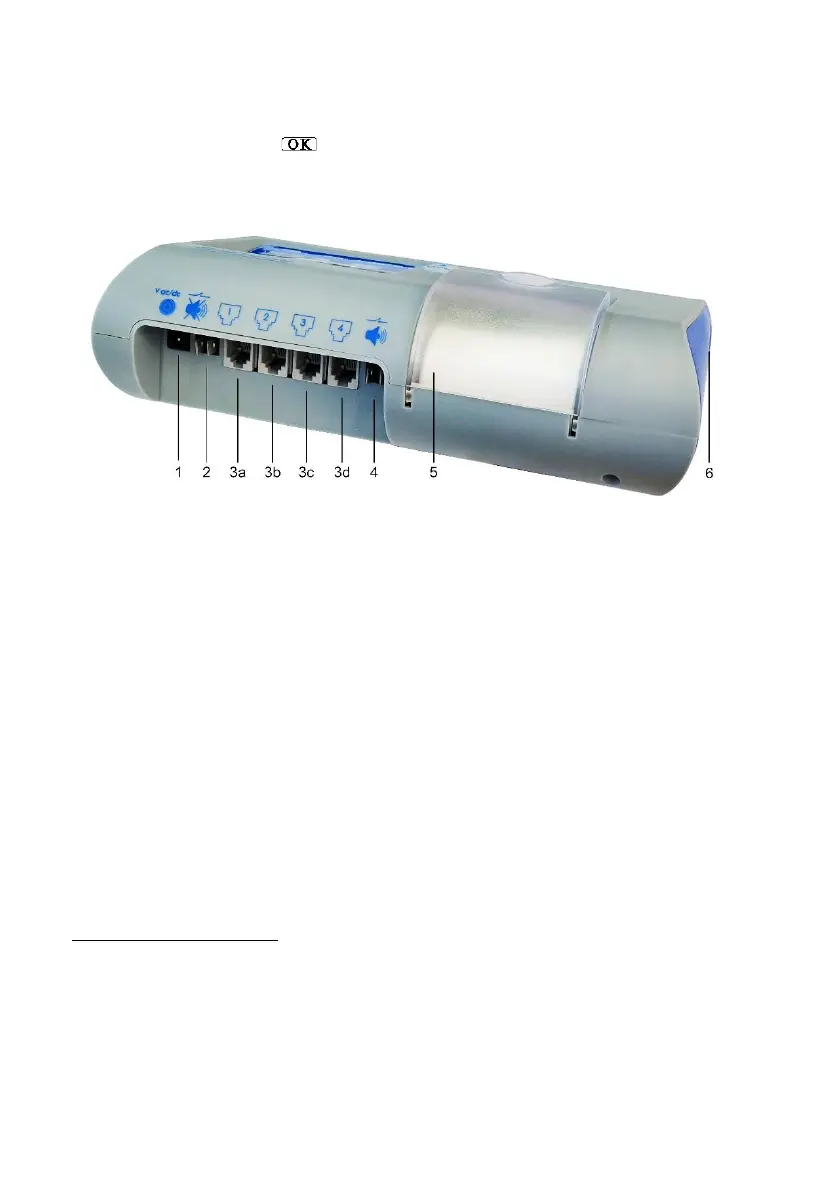
2. Connect the temperature, temperature/humidity sensors, circuit closing and other
sensors to the sockets (items 3a, 3b, 3c, 3d in Image 5) from left to right.
3. To turn on, press the key for 2 seconds (item OK item in Image 3), the green
POWER light and the display will turn on. After a few seconds, the measured
values will appear on the display.
Image 5: Connections
Other Connection Options
Other accessories (not included in all models) may be connected, as follows:
▲ External alarm contact – pair of ¼ terminals of an internal alarm relay, N.O. 1Amp 12V
(item 4 in Image 5). The contact closes in alarm events.
▲ Micro SD card – (not included) for saving a backup file to the measurement data in
addition to the internal memory and saving device settings for copying to another device
(Item 14 in Image 2). Recommended memory: 4GB to 16GB, Class 4 at least. In
installation, the contact surfaces are up. Press in to release the lock.
▲ USB disk-on-key – (not included) for saving a backup file of the measurement data in
addition to the internal memory and saving the device settings (for copying to another
device). (Item 2 Image 2). It is recommended to install a USB 2.0 disk-on-key up to 16GB.
▲ Remote alarm buzzer muter – (not included) by connecting 2 wires from the pair of the
buzzer muting contacts (item 2 in Image 5) to the momentary spring button. In an alarm, a
momentary short circuit between these contacts will silence the buzzer for this event (only
the buzzer!).
In the VLTSC model (GSM/GPS cellular model), the following can be installed also
when the device is turned off:
▲ GPS antenna to the GPS port (item 8 in Image 2) to display the location of the VLTS unit
on the map in the portal.
▲ GSM antenna to the GSM port (item 9 in Image 2).
▲ Micro-SIM Card (not included). Insert into the SIM slot (item 11 in Image 2), with the
contacts facing downward / toward the wall. For SMS notifications through an internal
cellular modem, data export to cloud and remote settings through the portal.