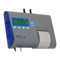
Temperature recorder and printer
7
CHAPTER 2 INSTALLATION
This chapter explains how to install the VLTS device, including:
▲ Package content – the list of contents in the VLTS package
▲ Installation options – options of installation, connection and hanging the device on the
wall
▲ Connections – description of the required connections and additional connection options,
including basic operating instructions for the VLTS device
▲ Power – the electrical power requirements, the Backup battery operating capacity and how
to install or replace batteries.
PACKAGE CONTENT
The VLTS package includes the following accessories:
Table 2: Package Content
VLTS
VLTSC (with internal cellular modem)
VLTS unit with up to 4 measurement channels
VLS CABLE (143168)
VLT PROBE
VLTSHPROBE
Event sensor, 10 meters (ON/OFF)
Temperature sensor, 10 m.
Temperature and humidity sensor, 10 m. meters
57 mm wide thermal paper roll, 40 meters long
for 17,400 lines of text
Transformer adapter from 230V to 12V 2A
12-30V DC plug wire for connection in vehicle
3V lithium battery (CR2032)
GSM/GPS integrated antenna for VLTSC
GSM “finger” antenna for VLTSC
GPS “finger” antenna for VLTSC
WALL INSTALLATION
VLTS may be used as a mobile unit or it may be installed on a wall.
▲ Wall installation – Hang the VLTS directly on the wall, on 2 horizontal screws 145 mm
apart and secure with a third screw to the wall under the paper rolls (3 screws and dowels
are provided in the bag).
CONNECTIONS
This part describes the cables that must be connected to enable use of the VLTS and other
accessories that may be connected for other, additional applications.
Mandatory connections and activation
To connect and operate the VLTS:
1. Connect the transformer to the power supply and the plug in the wire to the 12V
socket (item 1 in Image 5).