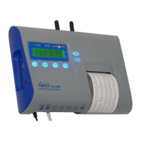
Temperature recorder and printer
5
DESCRIPTION
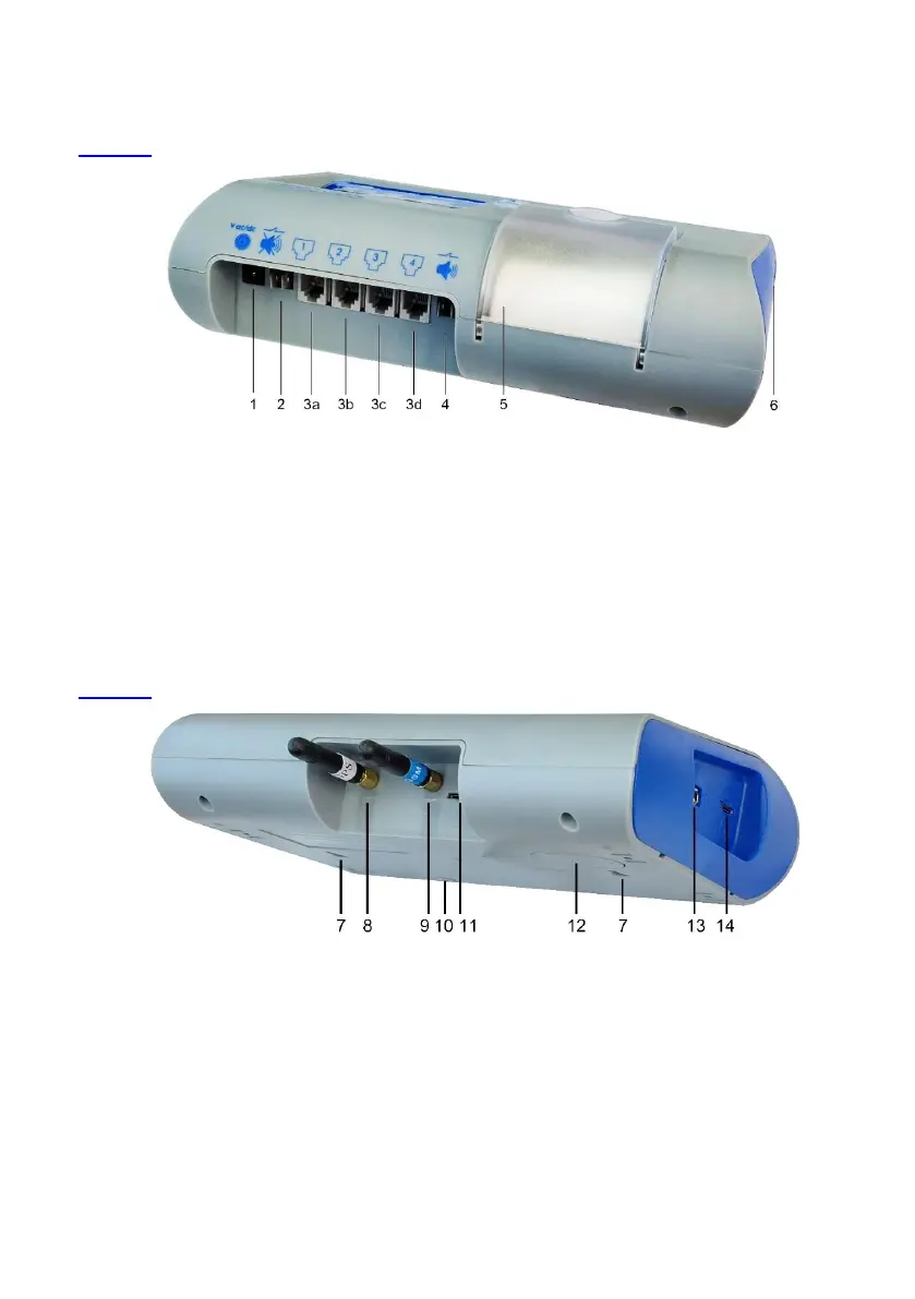
Image 1 displays the connections at the front of the VLTS/VLTSC device.
Image 1: Temperature Recorder and Printer – Front View – Connections
1. Power input socket: 12-24V ac/dc
4. Dry contact for external alarm
2. Short contacts for muting internal alarm
3. Sensor input ports 3b, 3c, 3d 3a,
6. 9V Backup battery cover
Image 2 displays the connections at the rear of the VLTS/VLTSC device.
Image 2: Temperature Recorder and Printer – Rear View
7. Holes for installing on wall
8. *GPS antenna port, SMA port
9. *GSM antenna port, SMA port
10. Hole to secure hanging on wall
11. Micro-SIM cellular card slot
12. CR2032 clock battery housing
13. USB disk-on-key connection
14. Micro-SD connection
* Items 8, 9, 11 are available only in model VLTSC.