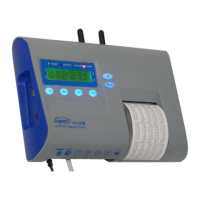
Temperature recorder and printer
18
LOADING SETTINGS FROM EXTERNAL MEMORY
Every time Settings saved is displayed upon exiting, the settings menu, a settings file,
named Config is saved in the external memory (USB or micro-SD, if installed). The Config
configuration file can be uploaded to any other VLTS device. The file does not copy ID
number, date, time and calibration data.
1. To load all the settings to the VLTS from an external memory device, find the Load
configuration file in the Settings submenu and press .
2. Load config. file will be displayed, and below it, flashing, one of the following options
will show: from USB memory or from micro-SD card. Select the appropriate option
by / or press to confirm.
Note: If the VLTS device fails to read from the selected device, an error message will be
displayed: Reading from… failed and the device will revert to the readings screen.
3. When loading the settings, the message Load config. file will be displayed for about
30 seconds.
4. After loading, the settings will be saved and Please wait saving settings will be
displayed for about 10 seconds, after which the display will revert to the readings
screen.
SETTING SENSOR TYPES
▲ Temperature – temperature sensor only
▲ Humid/Temp – an integrated temperature and humidity sensor, which sends data to 2
channels
▲ Humidity – setting an integrated temp. and humidity sensor to measure humidity only
▲ Contact Switch – on/off sensor for opening a dry contact (electric)
▲ VDC 0-10Vdc – dc voltage sensor, can be set for a unit and correlation
▲ VDC 0-5Vdc – dc voltage sensor, can be set for a unit and correlation
▲ IDC 0-20mAdc – dc voltage sensor, can be set for a unit and correlation
▲ IDC 4-20mAdc – dc voltage sensor, can be set for a unit and correlation
▲ Input power – measures the voltage supplied to the VLTS device.
▲ No sensor – channel without a sensor (the device will not read data from this channel)
The VLTS device has 4 input RJ45 ports to sensors (items 3a-d in Image 5). One sensor can
be connected to each of the ports according to the following list, and the sensor must
be configured accordingly.
1. Press / for the Setting submenu.
2. Press to confirm entering the Setting submenu. Enter password will be displayed.
4. Enter password (4 consecutive characters). If you have not yet changed the password, use
the default password: , , , .
5. Press / until the Set sensor type menu is displayed, and press .
6. The channel numbers (1-4) for selection will appear, for example Select Channel No. 1.
To change the channel number, press / until the desired channel appears, then
press .
7. The sensor name, such as Sensor 1 type will appear, and the type of sensor set for the
channel. To change the sensor type, press / . When selecting, * will appear to the
right of the sensor type not yet selected. To confirm the selected sensor, press , and a
confirmation, such as Channel No. 1 set, will appear. To select another channel number
to configure the sensor, press / or to exit.