Chapter 5: Advanced Motherboard Setup
5-15
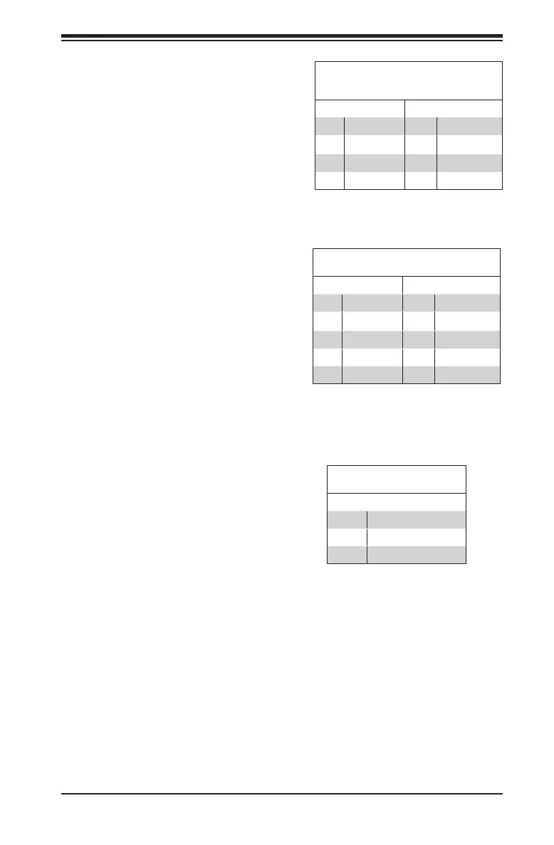
Serial Link General-Purpose Headers
(SGPIO)
Pin Denitions
Pin# Denition Pin Denition
1 NC 2 NC
3 Ground 4 DATA Out
5 Load 6 Ground
7 Clock 8 NC
I-SGPIO1/I-SGPIO2
Two Serial Link General Purpose In-
put/Output (SGPIO) headers are used
to communicate with the enclosure
management chip in the system. See
the table on the right for pin deni-
tions. Refer to the board layout below
for the locations of the headers.
GPIO Expander
Pin Denitions
Pin# Denition Pin Denition
1 P3V3 2 GND
3 GP0 4 GP1
5 GP2 6 GP3
7 GP5 8 GP5
9 GP6 10 GP7
GPIO Header (JGPIO1)
The JGPIO1 header is located near
the SATA connectors on the moth-
erboard. The JGPIO header is a
general-purpose I/O expander on a
pin header via the SMBus. See the
table on the right for pin denitions.
Refer to the board layout below for
the locations of the headers.
NVMe I2C Header
Connector JNVI2C is a management header for the Supermicro AOC NVMe PCI-E
peripheral cards. Connect it with the I2C cable.
System Management Bus Header
A PCH System Management Bus
header for additional slave devices or
sensors is located at JSMB1. See the
table on the right for pin denitions.
SMBus Header
Pin# Denition
1 Data
2 Ground
3 Clock

 Loading...


