49
Chapter 4: Motherboard Connections
Chapter 4
Motherboard Connections
The LEDs on the motherboard are also described here. A motherboard layout indicating
component locations may be found in Chapter 1.
Please review the Safety Precautions in Chapter 3 before installing or removing components.
4.1 Headers and Connectors
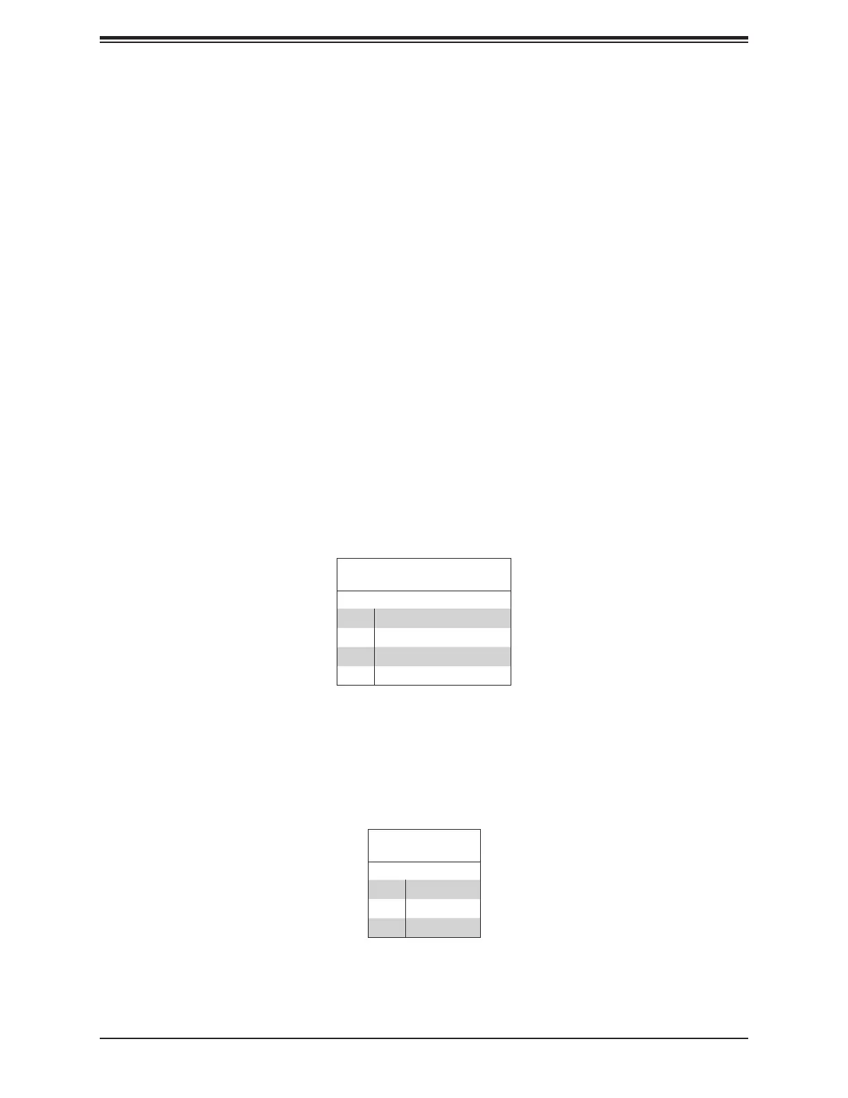
Onboard Fan Header
There are two fan headers on the motherboard. These are 4-pin fan headers; pins 1-3 are
backward compatible with traditional 3-pin fans. The onboard fan speeds are controlled
by Thermal Management (via Hardware Monitoring) in the BMC. When using Thermal
Management setting, use all 4-pin fans.
Fan Header
Pin Denitions
Pin# Denition
1 Ground (Black)
2 +12V (Red)
3 Tachometer (Yellow)
4 PWM Control (Blue)
Disk-On-Module Power Connector
The Disk-On-Module (DOM) power connector at JSD1 provides 5V power to a solid-state
DOM storage device connected to one of the SATA ports.
Note: DOM is recommended for OS boot or any none read/write in sensitive applications only.
DOM Power
Pin Denitions
Pin# Denition
1 5V
2 Ground
3 Ground