Chapter 2: Installation
2-13
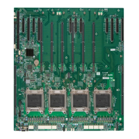
X10QBi
Rev:1.01B
MAC CODE
BAR CODE
CPU4
CPU3
CPU1
CPU2
MAC CODE
SMI Slot P1M1 (for CPU1 DIMM1)
SMI Slot P1M2 (for CPU1 DIMM2)
SMI Slot P2M1 (for CPU2 DIMM1)
SMI Slot P2M2 (for CPU2 DIMM2)
SMI Slot P3M1 (for CPU3 DIMM1)
SMI Slot P3M2 (for CPU3 DIMM2)
SMI Slot P4M1 (for CPU4 DIMM1)
SMI Slot P4M2 (for CPU4 DIMM2)
Installing Populated X10QBi Memory Cards on the Baseboard
1. After the memory card is populated with the desired number of RDIMM/
LRDIMM modules, it is ready to be installed on the baseboard.
2. Install one or two memory cards for each CPU installed on the baseboard,
starting with SMI Slot P1M1. The X10QBi baseboard supports up to four pro-
cessors. Refer to the table below to install memory cards that are populated
with DIMM modules to the X10QBi baseboard.
3. To fully utilize all onboard 11 PCI-E slots for the use of full-length add-on
cards, please install four DIMM modules in slots P1M2, P2M1, P3M2, P4M1,
and reserve slots P1M1 and P4M2. (See below.)
CPUs and the Corresponding Memory Cards
CPU# Corresponding DIMM Modules
No. of card(s) for
Each CPU
One (1) Memory Card for each CPU
Installed
Two (2) Memory Cards for each CPU
Installed
CPU 1 SMI Slot P1M1 SMI Slot P1M1 + SMI Slot P1M2
CPU 2 SMI Slot P2M1 SMI Slot P2M1 + SMI Slot P2M2
X10QBi-MEM1
 Loading...


