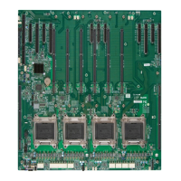
JXDP1
JIPMB1
JPI2C1
JD1
T-SGPIO1
T-SGPIO2
I-SATA0
I-SATA1
I-SATA2
I-SATA5
I-SATA4
I-SATA3
JF1
JIO1
SMI SLOT P4M1
SMI SLOT P3M2
SMI SLOT P3M1
SMI SLOT P2M2
SMI SLOT P2M1
SMI SLOT P1M2
SMI SLOT P4M2
SMI SLOT P1M1
CPU4
CPU3
CPU1
USB2/3
USB4
COM1
CPU4 SLOT8 PCI-E 3.0 X8
CPU4 SLOT10 PCI-E 3.0 X8
CPU4 SLOT11 PCI-E 3.0 X16
CPU3 SLOT7 PCI-E 3.0 X8
CPU3 SLOT6 PCI-E 3.0 X8
CPU3 SLOT9 PCI-E 3.0 X16
CPU2 SLOT5 PCI-E 3.0 X8
CPU2 SLOT3 PCI-E 3.0 X8
CPU1 SLOT2 PCI-E 3.0 X16
CPU1 SLOT1 PCI-E 3.0 X8
SIO SLOT
CLOSE 1st
OPEN 1st
CPU2
USB0/1
JI2C1
CLOSE 1st
OPEN 1st
CLOSE 1st
OPEN 1st
CLOSE 1st
OPEN 1st
M*
M*
M* M*
M*
M*
M*
M*
MAC CODE
JPW1
CPU2 SLOT4 PCI-E 3.0 X16
USB5
JVRMCPU1
A
4
JVRMCPU2
JVRMCPU3
JVRMCPU4
1
JPW4
JPW5
JPW6
JPW7
2-5 Installing the System Motherboard into the Chassis
Follow the instructions below to install the system motherboard into the chassis.
Tools Needed
• Phillips Screwdriver
• Pan_head #6 screws (20 pieces)
• Standoffs (20 pieces, if needed)
1. Install the I/O shield into the chassis.
2. Locate the mounting holes on the system system board and the matching
mounting holes on the chassis.
3. Place the system board into the chassis, making sure that the mounting holes
on the system board match the corresponding mounting holes on the chassis.
4. Install standoffs in the chassis as needed.
5. Using the Phillips screwdriver, insert a pan head #6 screw into a mounting
hole on the system board and its matching mounting hole on the chassis.
Repeat this step for other mounting holes to secure the system board to the
chassis.
 Loading...


