EasyManua.ls Logo

Supermicro x10qbi - Overheat (Oh);Fan Fail;Pwr Fail;Uid LED; Power Fail LED

Supermicro x10qbi
127 pages
To Next Page IconTo Next Page
To Previous Page IconTo Previous Page
Loading...
Chapter 2: Installation
2-27
Power Button
Red (OH/Fan Fail/
PWR FaiL)
1
NIC1 Link LED
Reset Button
2
Power Fail LED
HDD LED
FP PWRLED
Reset
PWR
3.3V
3.3V
Blue Led Cathode
(UID)
Ground
Ground
1920
3.3V
X
Ground
NMI
X
NIC2 Link LED
NIC2 Active LED
NIC1 Active LED
X10QBi
Rev:1.01B
MAC CODE
BAR CODE
M*M*M*M*M*M*
FAN5
FAN10
FAN7
FAN6
FAN8
FAN9
FAN1
FAN4
FAN2
FAN3
JPW2
JPW3
LED_PORT80
JM2
JM5
JLPC1
JP2
BT2
SP1
JP3
JL1
J17
JOH1
JI2C2
LED28
LED23
LED2
LED1
LED15
LED19
LED22
LED18
JBT1
LED35
LED10
LED9
LED8
LED14
LED7
LED12
LED13
LED11
LEDIO1
LED3
JSD1
JP1JP5
JPME2
JPME1
JWD1
JPT1
JWP1
JXDP3
JXDP2
JVRM_I2C1
JVRM_I2C2
JXDP1
JIPMB1
JPI2C1
JD1
T-SGPIO1
T-SGPIO2
I-SATA0
I-SATA1
I-SATA2
I-SATA5
I-SATA4
I-SATA3
JF1
JIO1
SMI SLOT P4M1
SMI SLOT P3M2
SMI SLOT P3M1
SMI SLOT P2M2
SMI SLOT P2M1
SMI SLOT P1M2
SMI SLOT P4M2
SMI SLOT P1M1
CPU4
CPU3
CPU1
USB2/3
USB4
COM1
CPU4 SLOT8 PCI-E 3.0 X8
CPU4 SLOT10 PCI-E 3.0 X8
CPU4 SLOT11 PCI-E 3.0 X16
CPU3 SLOT7 PCI-E 3.0 X8
CPU3 SLOT6 PCI-E 3.0 X8
CPU3 SLOT9 PCI-E 3.0 X16
CPU2 SLOT5 PCI-E 3.0 X8
CPU2 SLOT3 PCI-E 3.0 X8
CPU1 SLOT2 PCI-E 3.0 X16
CPU1 SLOT1 PCI-E 3.0 X8
SIO SLOT
CLOSE 1st
OPEN 1st
CPU2
USB0/1
JI2C1
CLOSE 1st
OPEN 1st
CLOSE 1st
OPEN 1st
CLOSE 1st
OPEN 1st
M*
M*
M* M*
M*
M*
M*
M*
MAC CODE
JPW1
CPU2 SLOT4 PCI-E 3.0 X16
USB5
JVRMCPU1
A
4
JVRMCPU2
JVRMCPU3
JVRMCPU4
1
JPW4
JPW5
JPW6
JPW7
B
Power Fail LED
The Power Fail LED connection is
located on pins 5 and 6 of JF1. Re-
fer to the table on the right for pin
denitions.
A. Front UID LED (Blue)
B. OH/ Fail/PWR Fail LED (Red)
C. PWR Supply Fail
A
C
PWR Fail LED
Pin Denitions (JF1)
Pin# Denition
5 3.3V
6 PWR Supply Fail
Overheat (OH)/Fan Fail/PWR Fail/
UID LED
Connect an LED cable to the OH/
Fan Fail/FP UID connection on pins
7 and 8 of JF1 to provide advanced
warnings of chassis overheating or
fan failure. It also works as the front
panel UID LED indicator. The red LED
takes precedence over the blue LED
by default. Refer to the table on the
right for pin denitions.
OH/Fan Fail/PWR Fail/UID LED
Pin Denitions (JF1)
Pin# Denition
7 Red+ (Blue LED Cathode)
8 Blue+ (OH/Fan Fail/PWR Fail/
UID LED)
OH/Fan Fail Indicator
Status
State Denition
Off Normal
On Overheat
Flash-
ing
Fan Fail
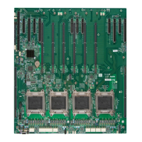
Table of Contents

Related product manuals