2-20
X10QBi Platform User's Manual
X10QBi
Rev:1.01B
MAC CODE
BAR CODE
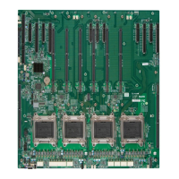
CPU4
CPU3
CPU1
CPU2
MAC CODE
2-7 I/O Module Connectors/Ports
The I/O ports are color coded in conformance with the PC Industry Standards. See
the picture below for the colors and locations of the various I/O ports.
Note: Before you power on the system, be sure to install the AOM-X10QBi-
A/L I/O module card into the SIO slot as shown in the gure. Without the I/O
module being installed on the baseboard, your system cannot be turned on.
SW1
LED28
JPB1
JPG1
JPL1
AOM-X10QBi-A/L
Rev. 1.02
SWUID1
JEDUID1
COM2
IPMI_LAN
LAN2
LAN1
VGA1
VGA2
LAN CTRL
BMC
AOM-X10QBi-A/L I/O Module
SIO Slot
I/O Port Locations and Denitions (See the Connector Section)
A. VGA1: VGA/Video Connector 1
B. LAN2: LAN Port2
C. LAN1: LAN Port1
D. (BMC) IPMI_LAN
E. UID (Unit Identier) Switch & UID LED (Blue: Unit Identied)
F. VGA2: VGA/Video Connector 2
G. COM2: COM Connection 2
1
2 3
Jumpers (See the Jumper Section)
1. JPL1: LAN Enable/Disable (Default: Pins 1-2: Enabled)
2. JPB1: BMC Enable/Disable (Default: Pins 1-2: Enabled)
3. JPG1: VGA Enable/Disable (Default: Pins 1-2: Enabled)
 Loading...


