2-8 Connecting Cables
A. JPW1: 24-pin ATX PWR (Req'd)
B. JPW2: 8-pin PWR (Req'd)
C. JPW3: 8-pin PWR (Req'd)
D. JPW4: 8-pin PWR (Req'd)
E. JPW5: 8-pin PWR (Req'd)
F. JPW6: 8-pin PWR (Req'd)
G. JPW7: 8-pin PWR (Req'd)
H. JSD1: SATA Device PWR (Req'd for
SATA devices)
A
B
C
H
DOM Power Connector
A power connector for SATA DOM (Disk-On-
Module) devices is located at JSD1. Con-
nect the appropriate cable here to provide
power support for your SATA DOM devices.
DOM PWR
Pin Denitions
Pin# Denition
1 +5V
2 Ground
3 Ground
Warning: To provide adequate power supply to
the system, be sure to connect the 24-pin ATX
PWR (JPW1) and six 8-pin PWR connectors
(JPW2-JPW7) to the power supply. Failure to
do so will void the manufacturer warranty on
your power supply and motherboard.
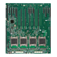
Power Connectors
A 24-pin main power supply connector(JPW
1) and six 8-pin power connectors (JPW2-
JPW7) are located on the X10DBi moth-
erboard. These power connectors meet
the SSI EPS 12V specication. Be sure to
connect these power connectors to your
power supply to provide adequate power to
your system. Refer to the table on the right
for pin denitions.
ATX Power 24-pin Connector
Pin Denitions
Pin# Denition Pin # Denition
13 +3.3V 1 +3.3V
14 -12V 2 +3.3V
15 COM 3 COM
16 PS_ON 4 +5V
17 COM 5 COM
18 COM 6 +5V
19 COM 7 COM
20 Res (NC) 8 PWR_OK
21 +5V 9 5VSB
22 +5V 10 +12V
23 +5V 11 +12V
24 COM 12 +3.3V
12V 8-pin PWR Con-
nector
Pin Denitions
Pins Denition
1 through 4 Ground
5 through 8 +12V
(Required)
 Loading...


