12
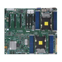
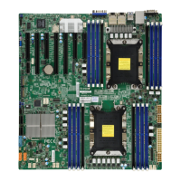
X11DPL-i User's Manual
Quick Reference Table
Jumper Description Default Setting
JBT1 Clear CMOS Open (Normal)
JPME2 Manufacturer (ME) Mode Select Pins 1-2 (Normal)
JVRM1 VRM SMB Clock (to BMC or PCH) Pins 1-2 BMC (Normal)
JVRM2 VRM SMB Data (to BMC or PCH) Pins 1-2 BMC (Normal)
JWD1 Watch-Dog Timer Enable Pins 1-2 (Reset)
Connector Description
Battery (BT1) Onboard CMOS battery
COM 1 Front Panel COM port 1
FAN1 ~ FAN6 System cooling fan headers
FANA/FANB Thermal fan headers for I/O add-on cards
IPMI_LAN Dedicated IPMI LAN port
(I-)SATA0~3, 4~7 I-SATA 3.0 connectors supported by the Intel PCH
J25 USB 2.0 Header for USB ports 2/3
J26 USB 3.0 Type A port for USB4
JF1 Front Control Panel header
JIPMB1 4-pin external BMC I²C header (for an IPMI card)
JL1
Chassis intrusion header (Note: please connect a cable from the Chassis Intrusion header at JL1
to the chassis to receive an alert via IPMI.)
JNVI
2
C1
NVMe SMBus (I
2
C) header used for PCI-E hot-plug SMBus clock & data connections (an SMCI-
proprietary NVMe add-on card and cable are required; available for a Supermicro complete system
only)
JPI²C1 Power Supply I²C connector
JPWR1/2 8-pin Power connectors
JPWR3 24-pin Power connectors
JRK1 RAID key for CPU NVME SSD
JSD1/JSD2 Power connector SATA DOM
JSDCARD1 Micro SD Card slot
JSTBY1 Wake On LAN header
JTPM1 Trusted Platform Module (TPM)/Port 80 connector
M.2 PCI-E M.2 slot
(S-)SATA0/1 S-SATA 3.0 connectors supported by the Intel PCH
SP1 Internal speaker
USB0/USB1 Back panel USB 2.0 ports
VGA Back panel VGA port
LED Description Status
LE1 UID (Unit Identier) LED Solid Blue: Unit Identied
LE6 Onboard Power LED
Solid Red: Standby
Solid Green: Power On
LEDM1 BMC Heartbeat LED Blinking Green: BMC Normal

 Loading...
