58
X11DPL-i User's Manual
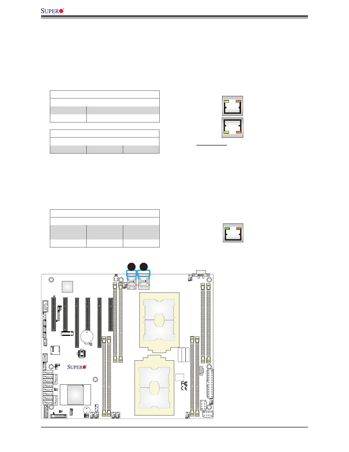
2.9 LED Indicators
LAN1/2 LEDs
LAN1 and LAN2 have two LED indicators respectively. The yellow LED on the left of the
LAN port indicates activity, while the amber LED on the right indicates the speed of the
connection. See the table below for more information.
GLAN Port 1/2 Activity Indicator LED Settings
Color Status Denition
Yellow Flashing Active
GLAN Port 1/2 Link Indicator LED Settings
Color Denition
Off No Connection
Amber 1Gbps
LAN1/2 LED
Activity LED Link LED
Rear View (when facing the
rear side of the chasis)
IPMI LAN LEDs
A dedicated IPMI LAN, located on the back panel, has two LED indicators. The amber LED
on the right of the IPMI LAN port indicates activity, while the green LED on the left indicates
the speed of the connection. See the table below for more information.
IPMI LAN LEDs
Color/State Denition
Link (left)
Green: Solid
Amber: Solid
100 Mbps
1Gbps
Activity (Right) Amber: Blinking Active
IPMI LAN LEDs
Activity LEDLink LED
1. IPMI LAN LEDs
2. LAN1/LAN2 LEDs
IPMI CODE
1
1
BIOS LICENSE
MAC CODE
BAR CODE
DESIGNED IN USA
X11DPL-i
REV:1.01
CPU1
CPU2
BMC
PCH
LE6
JSDCARD1
JTPM1
JUSB3
JRK1
LE1
SP1
JPI2C1
JPWR1
JPWR2
JBT1
JUIDB1
JSD1
JSD2
JLAN1
JPWR3
J26
JF1
JP2
JSTBY1
BT1
J25
JVRM1
JVRM2
JPME2
JWD1
JNVI2C1
LEDM1
LE2
FAN4 FAN3
FAN5
FAN2
FAN6
FAN1
FANB
FANA
SATA7
SATA8
SATA9
BIOS
M.2
JL1
JIPMB1
S-SGPIOI-SGPIO2I-SGPIO1
USB5/6(3.0)
USB2/3
USB4(3.0)
I-SATA7I-SATA6I-SATA5I-SATA4I-SATA3I-SATA2I-SATA1
S-SATA1
P2-DIMMA1
P2-DIMMB1
P1-DIMME1
P1-DIMMA1
P1-DIMMB1
P2-DIMME1
CPU1 SLOT6 PCI-E 3.0 X8
CPU1 SLOT2 PCI-E 3.0 X8
CPU2 SLOT3 PCI-E 3.0 X16
CPU1 SLOT5 PCI-E 3.0 X16
CPU1 SLOT4 PCI-E 3.0 X8
CPU1 SLOT1 PCI-E 3.0 X4 (IN X8)
S-SATA0
VGA
LAN1/2
COM1
P2-DIMMD1
P1-DIMMD1
USB0/1
IPMI_LAN
12

 Loading...


