29
Chapter 2: Installation
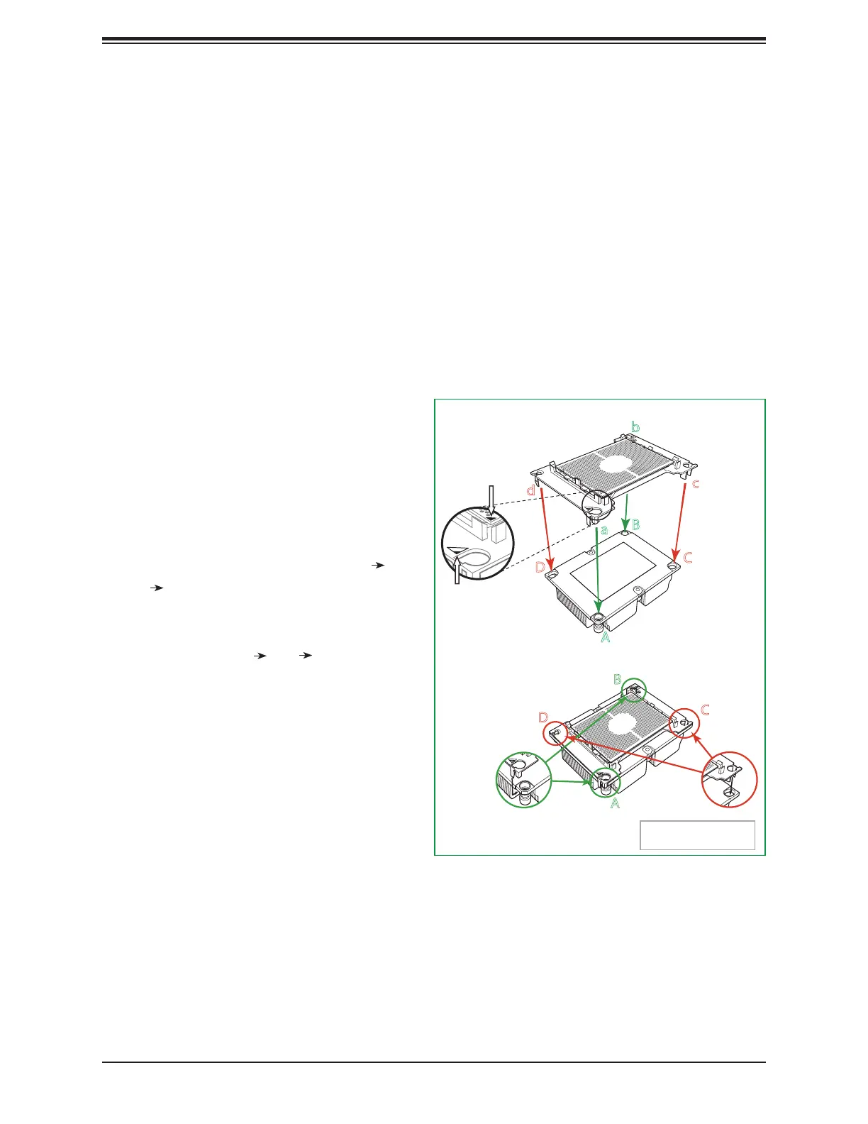
3. Align the larger holes (1, 2) on the
carrier against the larger mounting holes
(A, B) on the heatsink and smaller holes
(3, 4) on the carrier against the smaller
mounting holes (C, D) on the heatsink.
Insert the mounting clips next to the
larger hole on the carrier into the larger
mounting hole on the heatsink (1 A,
2 B) and snap the mounting clips next
to the smaller holes on the carrier onto
the edges of the heatsink next to the
smaller holes (3 C, 4 D) making sure
that the mounting clips snap into place,
and that the CPU/carrier assembly is
properly mounted onto the heatsink. By
mounting the CPU/carrier assembly to
the heatsink, the Processor Heatsink
Module (PHM) is assembled.
Attaching the CPU/Carrier Assembly to the Passive Heatsink to
Form the Processor Heatsink Module (PHM)
After you have made a CPU/carrier assembly, please follow the steps below to mount the
assembly onto the heatsink to create the Processor Heatsink Module (PHM).
1. Place the heatsink upside down with the thermal grease facing up. Locate two larger
mounting holes (A, B) at the diagonal corners of the heatsink, and two smaller mounting
holes (C, D) on the heatsink.
2. Hold the CPU/carrier at the center edge, and turn it upside down with the CPU pins
facing up. Locate the two larger holes (1, 2) at the diagonal corners of the carrier and
the smaller holes of the same size (3, 4) on the carrier. Please note the mounting clips
located next to every mounting hole on the carrier.
Heatsink
(Upside Down)
Non-Fabric CPU and Processor Clip
(Upside Down)
C
D
d
c
a
b
A
B
On Locations of (C, D), the notches
snap onto the heat sink’s
mounting holes
On Locations (A, B), the notches
snap onto the heatsink’s sides
A
B
D
C
Make sure Mounting
Notches snap into place
Triangle on the CPU
Triangle on the
Processor Clip

 Loading...


