52
X11DPL-i User's Manual
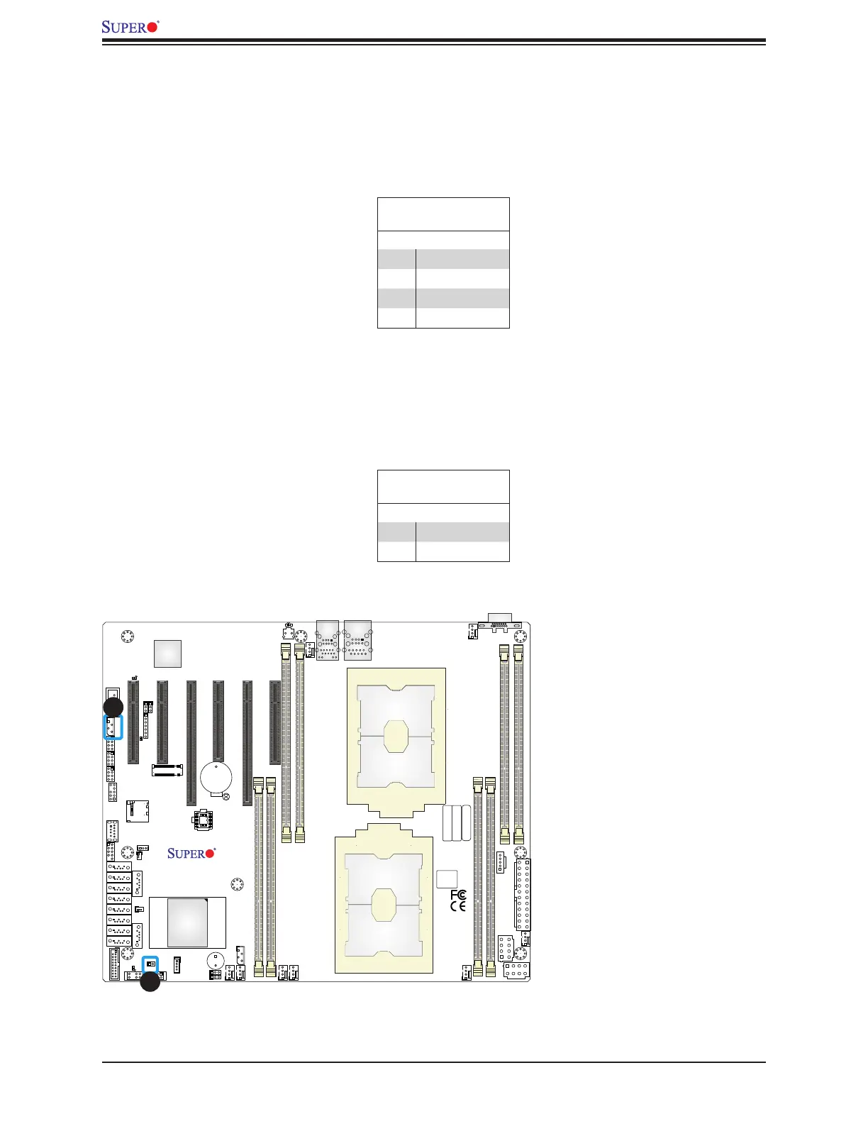
4-pin BMC External I2C Header
A System Management Bus header for IPMI 2.0 is located at JIPMB1. Connect the appropriate
cable here to use the IPMB I2C connection on your system. Refer to the table below for pin
denitions.
External I
2
C Header
Pin Denitions
Pin# Denition
1 Data
2 Ground
3 Clock
4 No Connection
Chassis Intrusion
A Chassis Intrusion header is located at JL1 on the motherboard. Attach the appropriate cable
from the chassis to inform you of a chassis intrusion when the chassis is opened. Refer to
the table below for pin denitions.
Chassis Intrusion
Pin Denitions
Pin# Denition
1 Intrusion Input
2 Ground
1. BMC External I
2
C Header
2. Chassis Intrusion
IPMI CODE
1
1
BIOS LICENSE
MAC CODE
BAR CODE
DESIGNED IN USA
X11DPL-i
REV:1.01
CPU1
CPU2
BMC
PCH
LE6
JSDCARD1
JTPM1
JUSB3
JRK1
LE1
SP1
JPI2C1
JPWR1
JBT1
JUIDB1
JSD1
JSD2
JLAN1
JPWR3
J26
JF1
JP2
JSTBY1
BT1
J25
JVRM1
JVRM2
JPME2
JWD1
JNVI2C1
LEDM1
LE2
FAN4 FAN3
FAN5
FAN2
FAN6
FAN1
FANB
FANA
SATA7
SATA8
SATA9
BIOS
M.2
JL1
JIPMB1
S-SGPIOI-SGPIO2I-SGPIO1
USB5/6(3.0)
USB2/3
USB4(3.0)
I-SATA7I-SATA6I-SATA5I-SATA4I-SATA3I-SATA2I-SATA1
S-SATA1
P2-DIMMA1
P2-DIMMB1
P1-DIMME1
P1-DIMMA1
P1-DIMMB1
P2-DIMME1
CPU1 SLOT6 PCI-E 3.0 X8
CPU1 SLOT2 PCI-E 3.0 X8
CPU2 SLOT3 PCI-E 3.0 X16
CPU1 SLOT5 PCI-E 3.0 X16
CPU1 SLOT4 PCI-E 3.0 X8
CPU1 SLOT1 PCI-E 3.0 X4 (IN X8)
S-SATA0
VGA
LAN1/2
COM1
P2-DIMMD1
P1-DIMMD1
USB0/1
IPMI_LAN
1
2

 Loading...


