2-10
X9DRW-3F/X9DRW-iF Motherboard User’s Manual
4. Once the heatsink is loosened, remove it from the motherboard.
Note: To reinstall the CPU and/or the heatsink, clean the surface of the
CPU and/or the heatsink to get rid of the old thermal grease. Reapply the
proper amount of thermal grease on the surface before reinstalling them
on the motherboard.
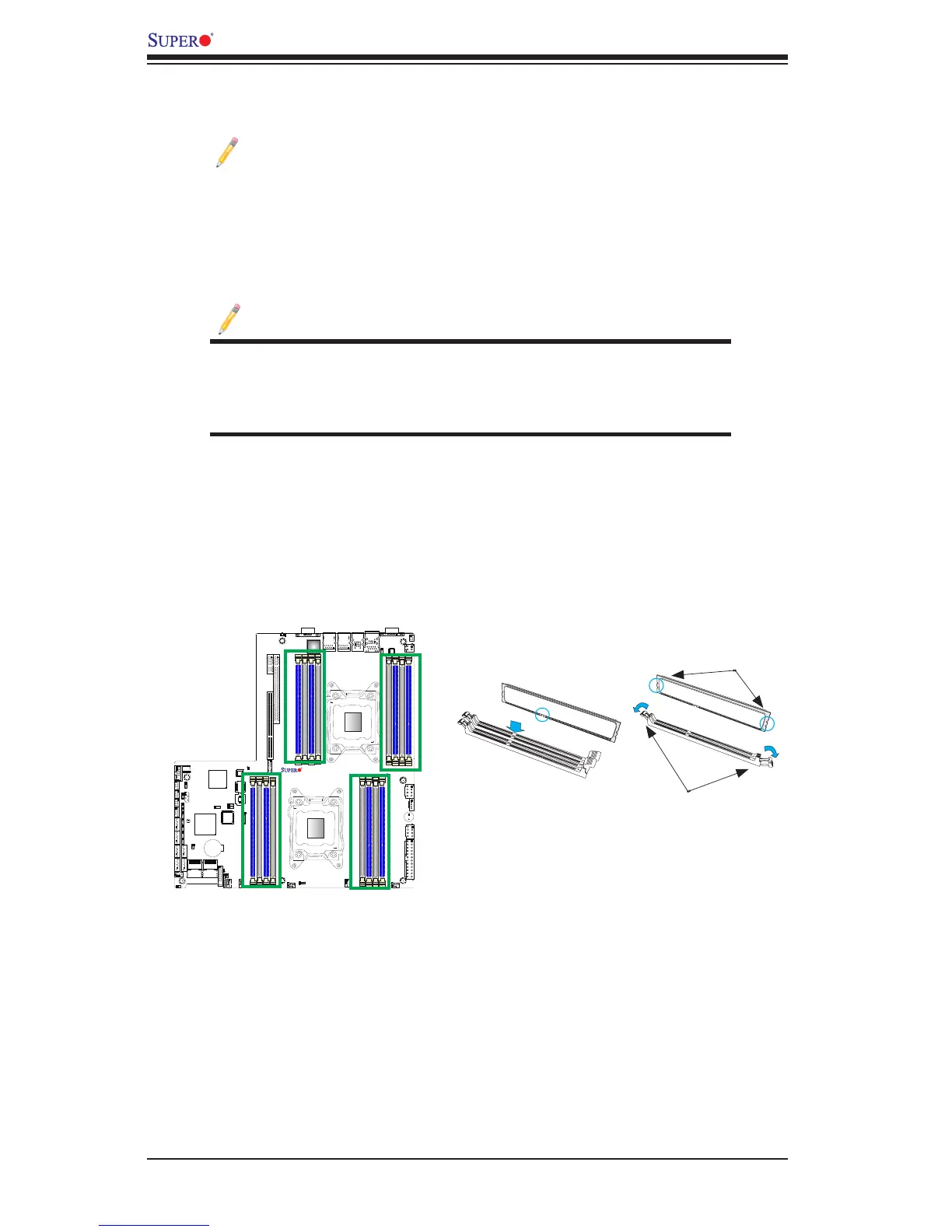
2-4 Installing and Removing the Memory Modules
Note: Check Supermicro's website for recommended memory modules.
CAUTION
Exercise extreme care when installing or removing DIMM
modules to prevent any possible damage.
Installing & Removing DIMMs
1. Insert the desired number of DIMMs into the memory slots, starting with
P1-DIMMA1. (For best memory performance, please use the modules of the
same type and speed in the same bank.)
2. Push the release tabs outwards on both ends of the DIMM slot to unlock it.
SP1
JPW3
JPW2
JPW4
JPB1
FAN2
FAN1
FAN4
FANA
FAN3
JPI2C1
LED3
LED1
COM2
JTAG OF CPLD
SXB1A
SXB1B: CPU PCI-E 3.0 x16 + x16
UID
SXB2: CPU2 PCI-E3.0 X16
LAN2
LAN1
USB2/3
USB0/1
IPMI-LAN
COM1
X9DRW-3F/iF
Rev.1.02
VGA
LAN
CTRL
BIOS
BMC
CTRL
JPW1
PHY
JPL1
B1
B2
A1
A2
B1
B2
A1
A2
SXB1C
JVRM_I2C2
JVRM_I2C1
JPG1
JIPMB1
JSTBY1
JSD1
JD1
JI2C1
JI2C2
JL1
JF1
I-SATA1
I-SATA0
JLPC1
JSM1
JSM2
T-SGPIO1
T-SGPIO2
I-SATA3
I-SATA2
I-SATA5
I-SATA4
JBAT1
JPME2
JWD1
JPME1
JP3
FANB
1
LED2
SATA/
USB4/5
PCH
JBT1
SCU0~3
SATA/
SCU4~7
JVR1
JUIDB
JOH1
P1-DIMMA1
P1-DIMMA2
P1-DIMMB1
P1-DIMMB2
P1-DIMMD2
P1-DIMMD1
P1-DIMMC2
P1-DIMMF1
P1-DIMME2
P1-DIMME1
P1-DIMMG1
P1-DIMMG2
P1-DIMMH1
P1-DIMMH2
CLOSE 1st
OPEN 1st
CPU1
CLOSE 1st
OPEN 1st
CPU2
P1-DIMMC1
P1-DIMMF2
Release Tabs
Notches
3. Align the DIMM module key with the receptive point on the memory slot.
4. Align the notches on the both ends of the module with the receptive points on
ends of the slot.
5. Use two thumbs together to press the notches of the module straight down
into the slot until the module snaps into place.
6. Press the release tabs to the locked positions to secure the DIMM module
into the slot.
 Loading...


