I-SATA2
I-SATA5
I-SATA4
JBAT1
JPME2
JWD1
JPME1
JP3
FANB
1
LED2
SATA /
USB4/5
PCH
JBT1
SCU0~3
SATA /
SCU4~7
JVR1
JUIDB
JOH1
P1-DIMMA1
P1-DIMMA2
P1-DIMMB1
P1-DIMMB2
P1-DIMMD2
P1-DIMMD1
P1-DIMMC2
P1-DIMMF1
P1-DIMME2
P1-DIMME1
P1-DIMMG1
P1-DIMMG2
P1-DIMMH1
P1-DIMMH2
CLOSE 1st
OPEN 1st
CPU1
CLOSE 1st
OPEN 1st
CPU2
P1-DIMMC1
P1-DIMMF2
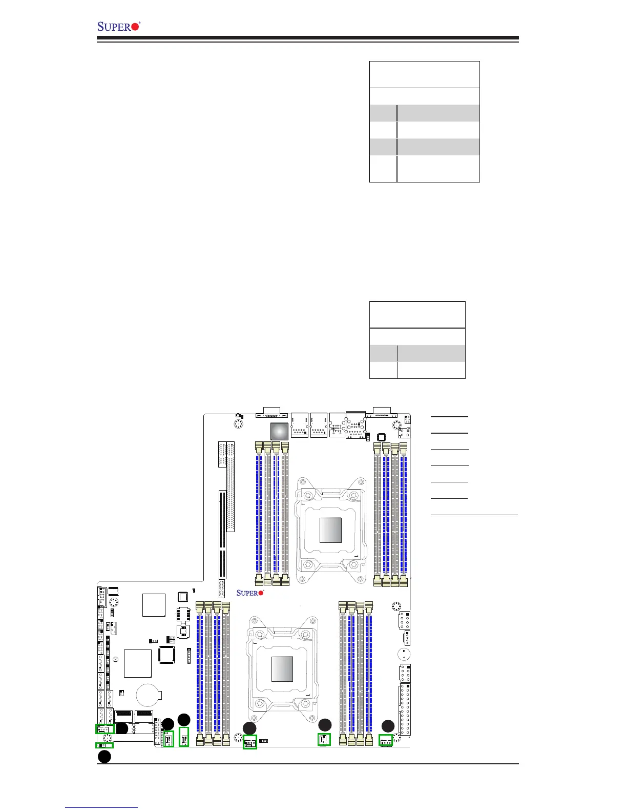
A. Fan 1
B. Fan 2
C. Fan 3
D. Fan 4
E. Fan A
F. Fan B
G. Chassis Intrusion
Chassis Intrusion
A Chassis Intrusion header is located
at JL1 on the motherboard. Attach an
appropriate cable from the chassis to
inform you of a chassis intrusion when
the chassis is opened.
Chassis Intrusion
PinDenitions
Pin# Denition
1 Intrusion Input
2 Ground
C
Fan Headers
This motherboard has six system/CPU
fan headers (Fan 1~Fan 4, Fan A, Fan B)
on the motherboard. All these 4-pin fans
headers are backward compatible with
the traditional 3-pin fans. The fan speeds
are controlled by rmware thermal man-
agement via IPMI 2.0. See the table on
the right for pin denitions.
Fan Header
PinDenitions
Pin# Denition
1 Ground
2 +12V
3 Tachometer
4 Firmware Thermal
Control
 Loading...


