NIC1/NIC2 LED Indicators
The NIC (Network Interface Control-
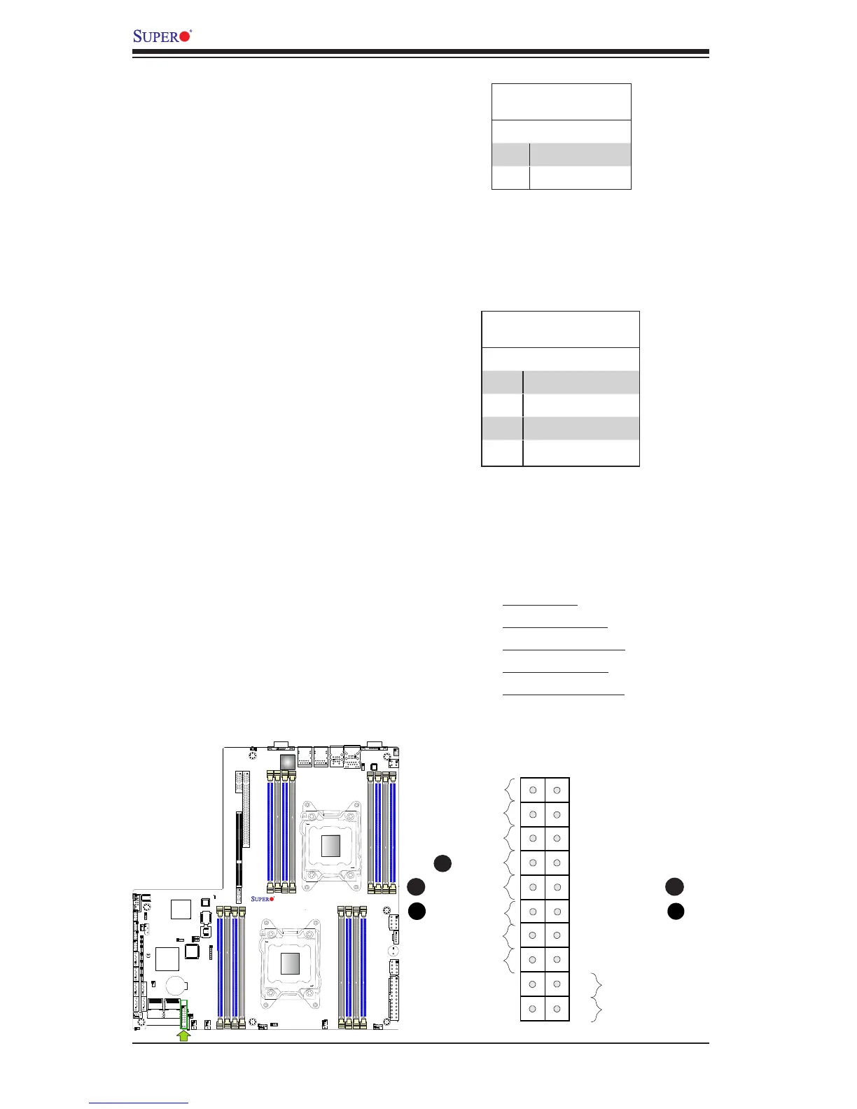
ler) LED connections for GLAN port 1
are located on pins 11 and 12 of JF1,
and the LED connection for GLAN
Port 2 are on Pins 9 and 10. Attach
the NIC LED cables here to display
network activity. Refer to the table on
the right for pin denitions.
HDD LED
The HDD LED connection is located
on pins 13 and 14 of JF1. Attach a
cable here to indicate HDD activ-
ity. See the table on the right for pin
denitions.
HDD LED
PinDenitions(JF1)
Pin# Denition
13 3.3V Standby
14 HD Active
A. HDD LED
B. NIC1 Link LED
C. NIC1 Activity LED
D. NIC2 Link LED
E. NIC2 Activity LED
GLAN1/2 LED
PinDenitions(JF1)
Pin# Denition
9 NIC 2 Activity LED
10 NIC 2 Link LED
11 NIC 1 Activity LED
12 NIC 1 Link LED
SP1
JPW3
JPW2
JPW4
JPB1
FAN2
FAN1
FAN4
FANA
FAN3
JPI2C1
LED3
LED1
COM2
JTAG OF CPLD
SXB1A
SXB1B: CPU PCI-E 3.0 x16 + x16
UID
SXB2: CPU2 PCI-E3.0 X16
LAN2
LAN1
USB2/3
USB0/1
IPMI-LAN
COM1
X9DRW-3F/iF
Rev.1.02
VGA
LAN
CTRL
BIOS
BMC
CTRL
JPW1
PHY
JPL1
B1
B2
A1
A2
B1
B2
A1
A2
SXB1C
JVRM_I2C2
JVRM_I2C1
JPG1
JIPMB1
JSTBY1
JSD1
JD1
JI2C1
JI2C2
JL1
JF1
I-SATA1
 Loading...


