I-SATA2
I-SATA5
I-SATA4
JBAT1
JPME2
JWD1
JPME1
JP3
FANB
1
LED2
SATA/
USB4/5
PCH
JBT1
SCU0~3
SATA/
SCU4~7
JVR1
JUIDB
JOH1
P1-DIMMA1
P1-DIMMA2
P1-DIMMB1
P1-DIMMB2
P1-DIMMD2
P1-DIMMD1
P1-DIMMC2
P1-DIMMF1
P1-DIMME2
P1-DIMME1
P1-DIMMG1
P1-DIMMG2
P1-DIMMH1
P1-DIMMH2
CLOSE 1st
OPEN 1st
CPU1
CLOSE 1st
OPEN 1st
CPU2
P1-DIMMC1
P1-DIMMF2
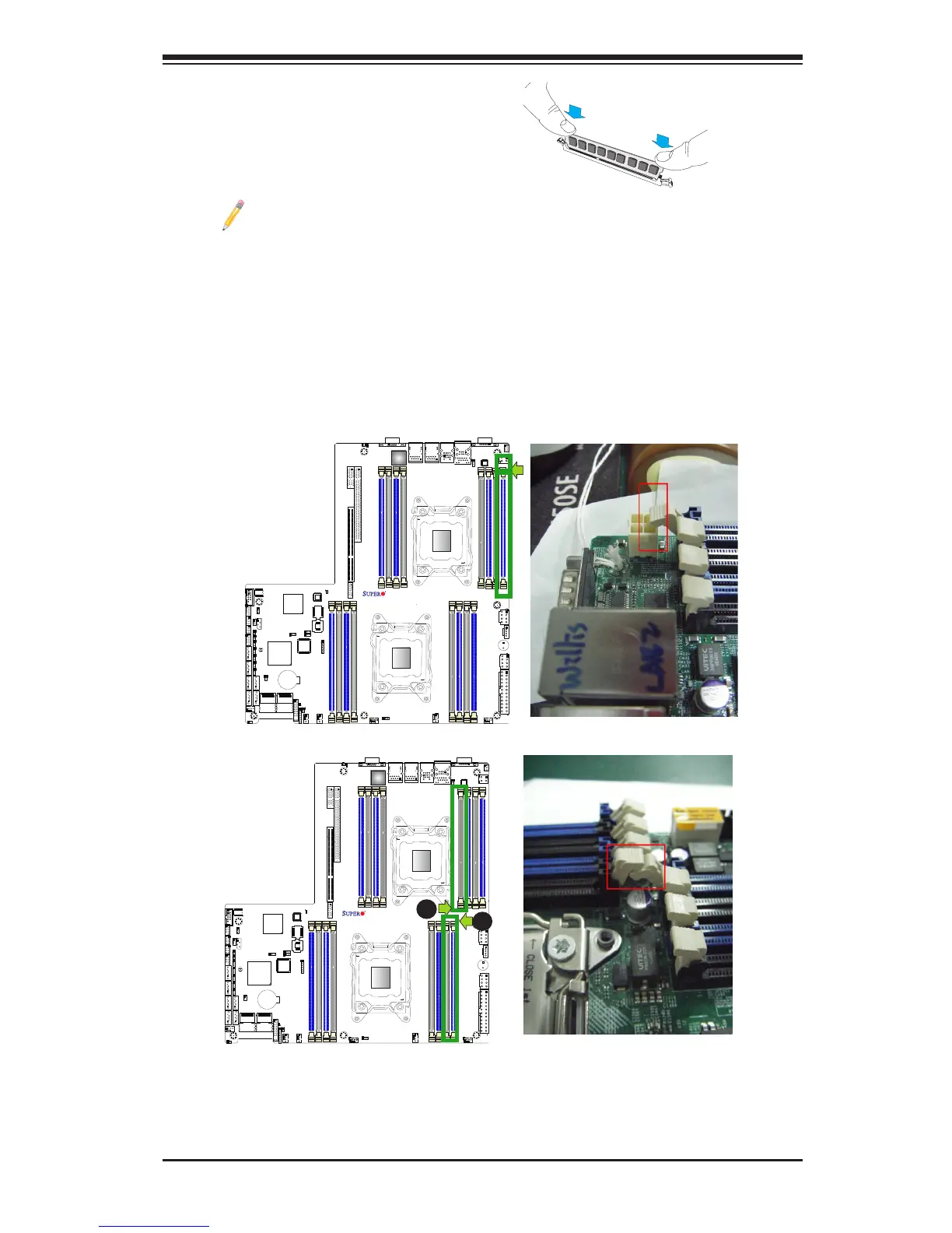
Removing Memory Modules
Press both notches on the ends of the DIMM module to unlock it. Once it is loos-
ened, remove it from the memory slot.
Notes:
Press both notches straight
down into the memory slot at
the same time.
1. For proper memory installation, be sure to install a DIMM module into
the P2-DIMMG1 slot before inserting a 4-pin power connector into JPW4
as shown in the graphics below.
2. To provide clearance for proper memory installation, please lock the
release tab at the end of P1-DIMMA1, marked "A", into the locking posi-
tion before inserting a DIMM module into the P2-DIMMH2 slot. Also, lock
the tab, marked "B", before installing a DIMM module into P1-DIMMA1.
SP1
JPW3
JPW2
JPW4
JPB1
FAN2
FAN1
FAN4
FANA
FAN3
JPI2C1
LED3
LED1
COM2
JTAG OF CPLD
SXB1A
SXB1B: CPU PCI-E 3.0 x16 + x16
UID
SXB2: CPU2 PCI-E3.0 X16
LAN2
LAN1
USB2/3
USB0/1
IPMI-LAN
COM1
X9DRW-3F/iF
Rev.1.02
VGA
LAN
CTRL
BIOS
BMC
CTRL
JPW1
PHY
JPL1
B1
B2
A1
A2
B1
B2
A1
A2
SXB1C
JVRM_I2C2
JVRM_I2C1
JPG1
JIPMB1
JSTBY1
JSD1
JD1
JI2C1
JI2C2
JL1
JF1
I-SATA1
I-SATA0
JLPC1
JSM1
JSM2
T-SGPIO1
T-SGPIO2
I-SATA3
I-SATA2
I-SATA5
I-SATA4
JBAT1
JPME2
JWD1
JPME1
JP3
FANB
1
LED2
SATA/
USB4/5
PCH
JBT1
SCU0~3
SATA/
SCU4~7
JVR1
JUIDB
JOH1
P1-DIMMA1
P1-DIMMA2
P1-DIMMB1
P1-DIMMB2
P1-DIMMD2
P1-DIMMD1
P1-DIMMC2
P1-DIMMF1
P1-DIMME2
P1-DIMME1
P1-DIMMG1
P1-DIMMG2
P1-DIMMH1
P1-DIMMH2
CLOSE 1st
OPEN 1st
CPU1
CLOSE 1st
OPEN 1st
CPU2
P1-DIMMC1
P1-DIMMF2
B
A
 Loading...


