Chapter 5: Advanced Serverboard Setup
5-17
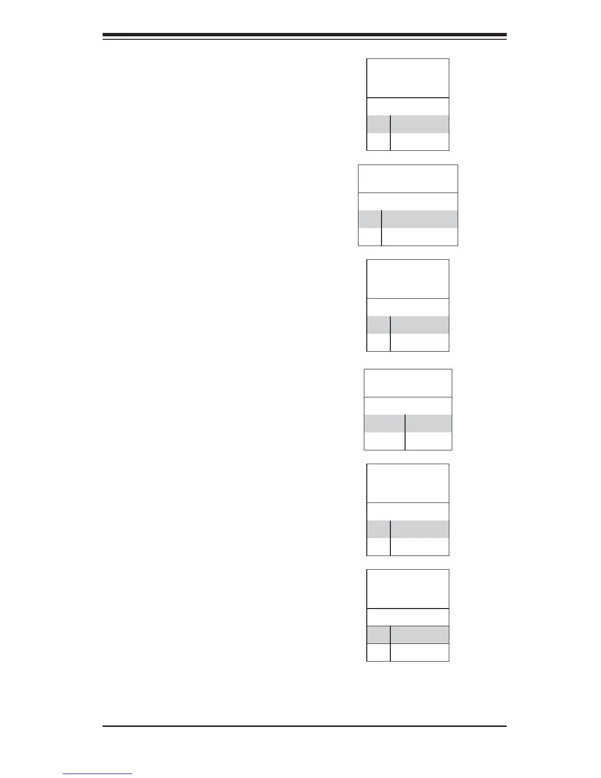
Reset Connector
The reset connector is located on pins
3 and 4 of JF1 and attaches to the
reset switch on the computer chassis.
See the table on the right for pin
defi nitions.
Reset Button
Pin Defi nitions
(JF1)
Pin# Defi nition
3 Reset
4 Ground
Overheat/Fan Fail LED (OH)
Connect an LED to the OH connection
on pins 7 and 8 of JF1 to provide
advanced warning of chassis
overheating or fan failure. Refer to the
table on the right for pin defi nitions and
status indicators.
OH/Fan Fail LED
Pin Defi nitions
(JF1)
Pin# Defi nition
7 Vcc
8 Control
OH/Fan Fail
LED Status
State Indication
Solid Overheat
Blinking Fan fail
Power Fail LED
The Power Fail LED connection
is located on pins 5 and 6 of JF1.
Refer to the table on the right for pin
defi nitions.
PWR Fail LED
Pin Defi nitions (JF1)
Pin# Defi nition
5 3.3V
6 PWR Supply Fail
NIC1 LED
Pin Defi nitions
(JF1)
Pin# Defi nition
11 Vcc
12 Ground
NIC1 (LAN1) LED
The LED connections for LAN1 are on
pins 11 and 12 of JF1. Attach LAN LED
cables to display network activity. See
the table on the right for pin defi nitions.
NIC2 (LAN2) LED
The LED connections for LAN2 are on
pins 9 and 10 of JF1. Attach LAN LED
cables to display network activity. See
the table on the right for pin defi nitions.
NIC2 LED
Pin Defi nitions
(JF1)
Pin# Defi nition
9 Vcc
10 Ground
 Loading...